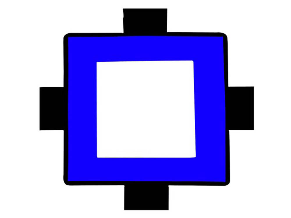
Blue Square Edge LED Backlight
Custom center through-hole structure for mechanical integration.

DisplayMan develops custom LED backlights around the LCD viewing area, housing, optical target and electrical interface.
Configure the outline, color, brightness, thickness, Light Guide Plate, optical films, PCB or FPC, wire, connector and PIN as one complete backlight component.
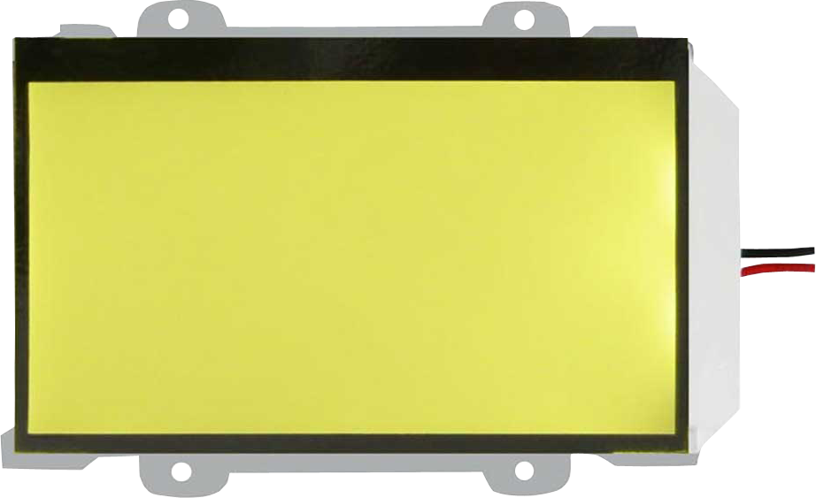
DisplayMan supplies custom LED Backlights for LCD displays, monochrome LCD modules, Segment LCD, Character LCD, Graphic LCD, Dot Matrix LCD and OEM display products.
LED Backlights provide a controlled light source behind or beside LCD glass, helping the display remain readable in indoor, low-light or controlled-lighting environments.
Customization can include backlight size, shape, thickness, color, brightness, uniformity, optical films, PCB or FPC, wire, connector, PIN and mechanical matching with the LCD module.
LED Backlight is the light-source component of an LCD system. It is not an LED Display and it is not an LCD Controller Board.
The correct direction depends on LCD type, brightness, color, size, thickness, optical structure, connection and product assembly.
| Product Direction | Best For | Selection Logic |
|---|---|---|
| Edge LED Backlights | Thin LCD modules and side-light structures | Selected when LED light enters from one or more edges of the light guide plate |
| Bottom LED Backlights | Direct illumination and selected simple backlight structures | Selected when LEDs are placed behind the display area |
| LED Backlight for Segment LCD | Custom LCD glass, meters, appliances and fixed icons | Selected when digits, icons or symbols need illumination |
| LED Backlight for Character LCD | 16×2, 20×4 and other character LCD modules | Selected when text-based monochrome LCD needs backlight support |
| LED Backlight for Graphic LCD | 128×64, 240×128 and similar graphic LCD modules | Selected when pixel-based monochrome LCD needs uniform illumination |
| Custom Shape LED Backlights | Special LCD glass and non-standard product housings | Selected when a standard rectangular backlight cannot match the product |
| Through-Hole LED Backlights | Modules requiring holes, screws or special mechanical openings | Selected when the backlight must match structural openings |
| LED Backlight with Wire / Connector / PIN | OEM LCD-module and product-PCB integration | Selected when the electrical connection must match the final assembly |
LED Backlight normally needs LCD glass, polarizers, driver electronics and mechanical structure to become a complete LCD module.
These examples show common custom directions, not fixed standard models.
Custom center through-hole structure for mechanical integration.
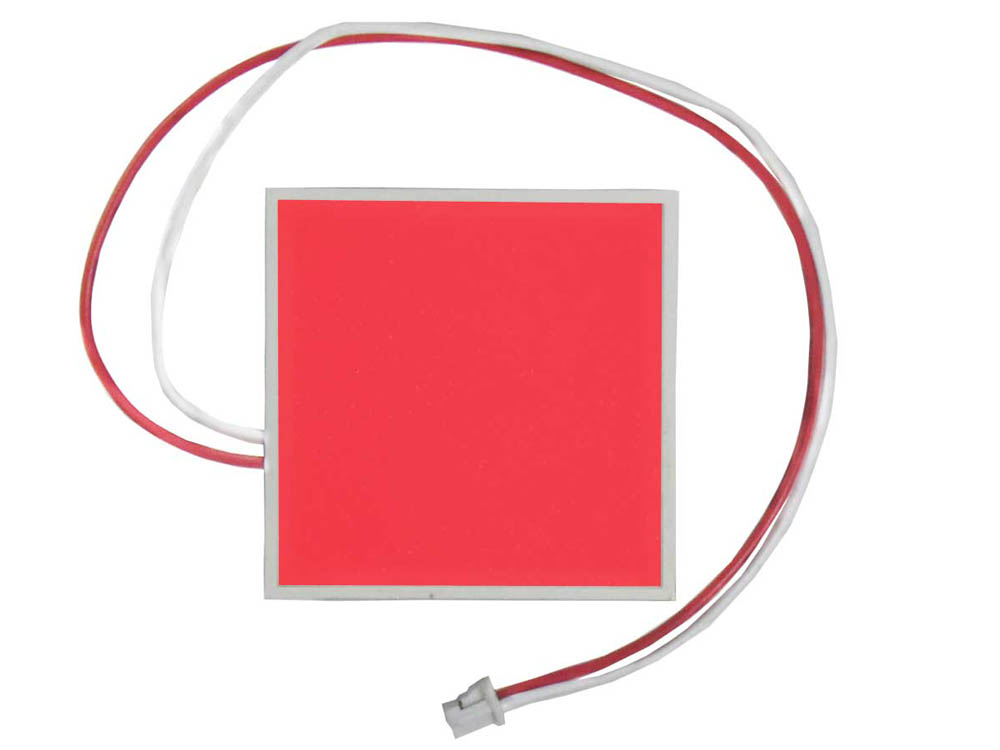
Compact direct-light structure with wire connection.
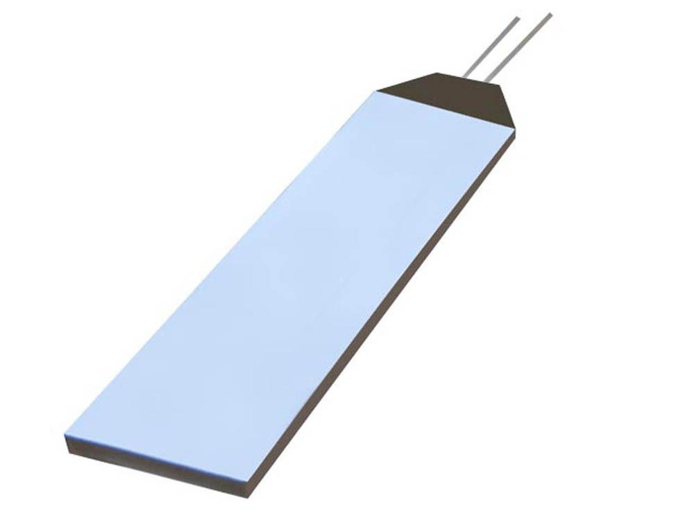
Edge-lit rectangular construction for direct PCB assembly.
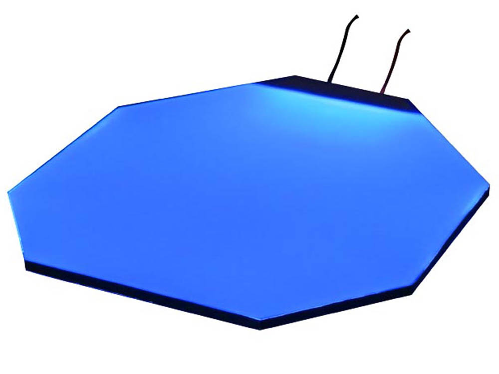
Non-standard polygon outline with a flexible wire interface.
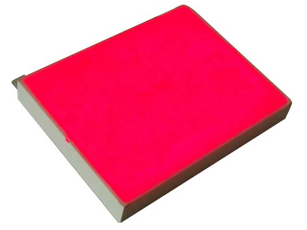
Rigid electrical interface for repeatable module assembly.
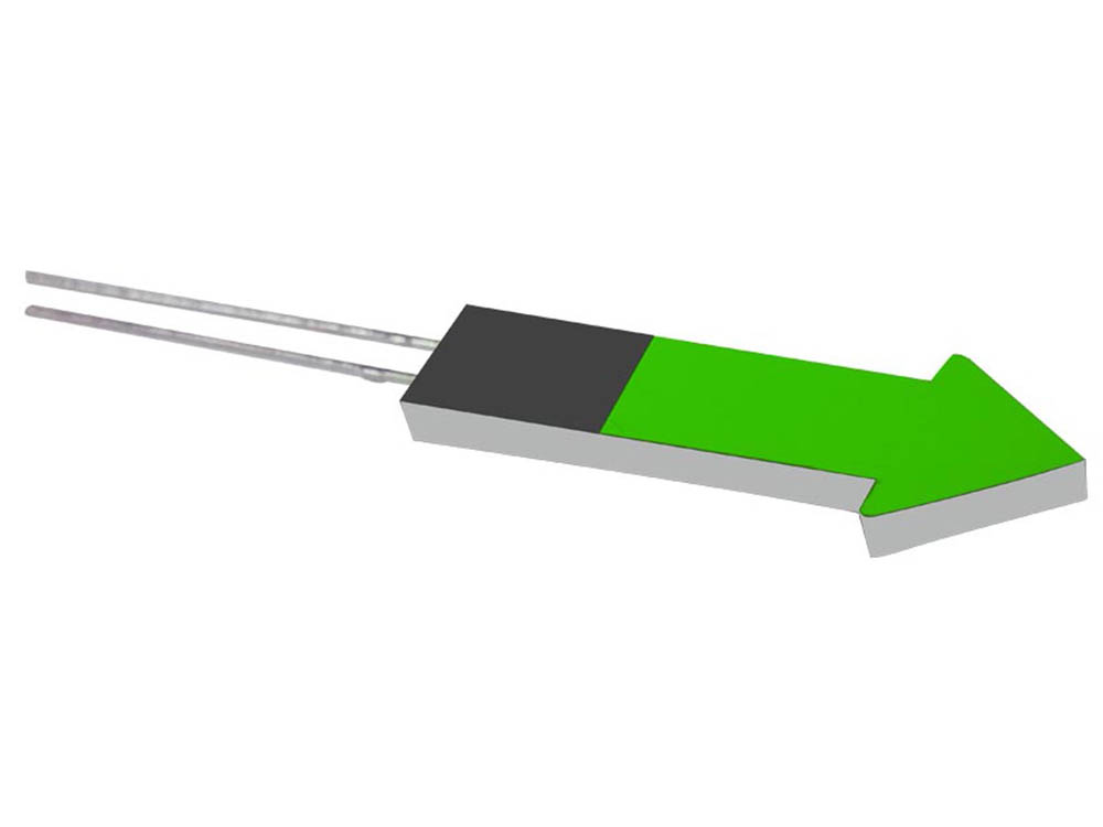
Custom symbol outline showing shape-specific optical design.
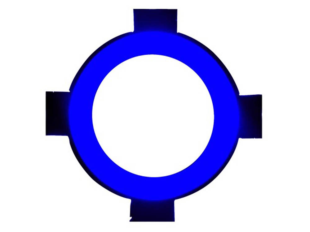
Circular through-hole design for controls, meters and interfaces.
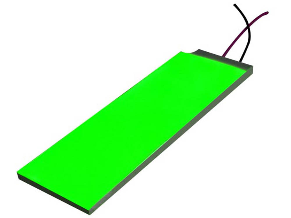
Custom-size illumination component with remote connection.
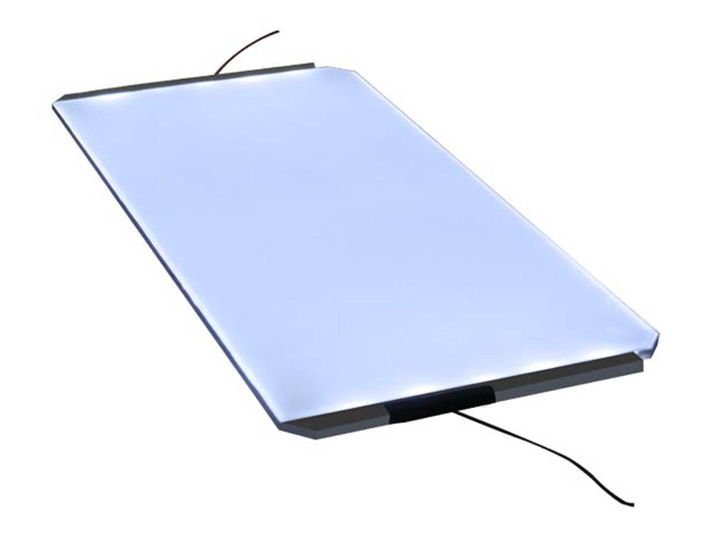
General-purpose white illumination for monochrome LCD modules.
| Backlight Type | Size | Color | Application | Connection |
|---|---|---|---|---|
| Edge LED Backlight | Custom / through-hole | Blue | LCD module backlight or illumination | Wire |
| Bottom LED Backlight | Custom | Red | LCD module backlight or illumination | Wire + connector |
| Edge LED Backlight | Custom | White | Monochrome LCD display | Metal PIN |
| Edge LED Backlight | Custom | Blue | Monochrome LCD display | Wire |
| Edge LED Backlight | Custom / through-hole | Red | Monochrome LCD display | Hard PIN |
| Edge LED Backlight | Custom | Green | LCD module backlight or illumination | Metal PIN |
| Edge LED Backlight | Custom / through-hole | Blue | LCD module backlight or illumination | Wire |
| Edge LED Backlight | Custom | White | Monochrome LCD display | Wire |
Final brightness, uniformity, LED position, Light Guide Plate, film stack, thickness and connection must be confirmed together.
Provides the light source needed by transmissive and transflective LCD structures.
Uses a Light Guide Plate and films to distribute light across the viewing area.
Includes LEDs, PCB or FPC, connection and product-specific mechanical matching.
LED Backlights are selected when an LCD needs controlled illumination for readability and product appearance.
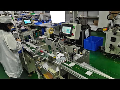
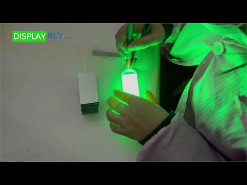
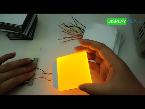
Real production footage shows how the backlight is assembled and inspected. The two technical videos explain the illumination principle and the definition of an edge-lit backlight.
 ▶
▶ ▶
▶ ▶
▶ ▶
▶ ▶
▶ ▶
▶| Factor | Edge LED Backlight | Bottom LED Backlight |
|---|---|---|
| LED Position | LEDs enter from one or more edges | LEDs are placed behind the display area |
| Light Distribution | Relies strongly on the Light Guide Plate | Relies on LED spacing and diffusion |
| Thickness | Can be thinner | Usually thicker |
| Uniformity Design | Dot pattern and film stack are critical | LED spacing and diffusion distance are critical |
| Best For | Thin LCD modules and side-light structures | Direct illumination and selected simple structures |
| Selection Logic | Choose when module thickness matters | Choose when direct illumination is more practical |
Choose Edge LED for a thinner side-light structure. Choose Bottom LED when direct illumination is more suitable for the module design.
Common general-purpose direction for monochrome LCD modules and product displays.
Selected for specific visual effects, product styling and replacement projects.
Used for meters, instruments and selected legacy-style displays.
Used for warning, instrument and product-design effects.
Common in selected industrial, instrument and legacy applications.
Project-based LED colors can be reviewed with the LCD mode and polarizer.
Backlight color should be reviewed with the LCD display mode, polarizer, printed overlay, readability and final product appearance.
Uniformity and brightness are created by the complete optical and electrical stack. These are representative materials and components used in custom backlight construction.
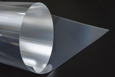
Brightness Enhancing Films (BEF) play a pivotal role in enhancing the display’s luminance while saving on energy consumption. They are available in different versions, including Prismatic, Microlens, and Lenticular, each offering unique benefits. These films effectively increase display brightness, making content more vivid and sharp, all while conserving energy. This not only leads to lower power consumption but also extends battery life, a valuable feature in our mobile-driven world.
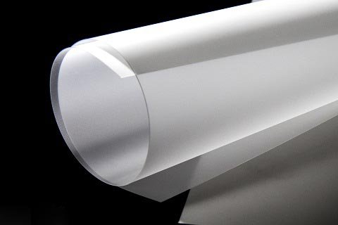
In the quest for uniform and brilliant backlighting, diffusion films and reflective films are indispensable. They serve a dual purpose: increasing brightness while ensuring even illumination across the entire display. These films are key in controlling viewing angles, resulting in displays that are clear and visible from various perspectives. The combination of diffusion and reflective films contributes to a visually appealing and consistent lighting solution.
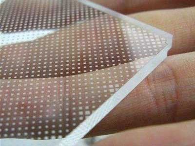
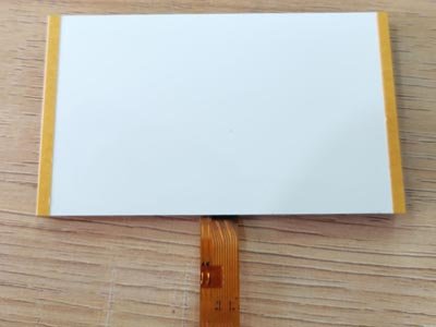

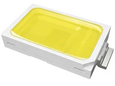
| Component | Main Function | Main Review Factors |
|---|---|---|
| LED Lamps | Light source | LED type, color, brightness, current, quantity and position |
| Light Guide Plate | Distributes edge light across the area | Dot pattern, thickness, light direction and tooling |
| Diffusion Film | Improves uniformity | Reduces bright spots and spreads light |
| Reflective Film | Redirects light toward the LCD | Improves light utilization |
| Brightness Enhancement Film | Improves front brightness | Used when higher efficiency is required |
| Light-Blocking Film | Controls light leakage | Matches the viewing area and mechanical opening |
| PCB or FPC | Carries LEDs and electrical connection | Selected by thickness, flexibility and assembly |
| Wire / Connector / PIN | Connects backlight to the product PCB | Voltage, current, polarity and serviceability |
Backlight performance depends on LEDs, Light Guide Plate, optical films, thickness, viewing area and mechanical structure—not only the nominal LED brightness.
Production combines PCB preparation, LED placement and soldering, optical-film assembly, Light Guide Plate integration and staged quality inspection.
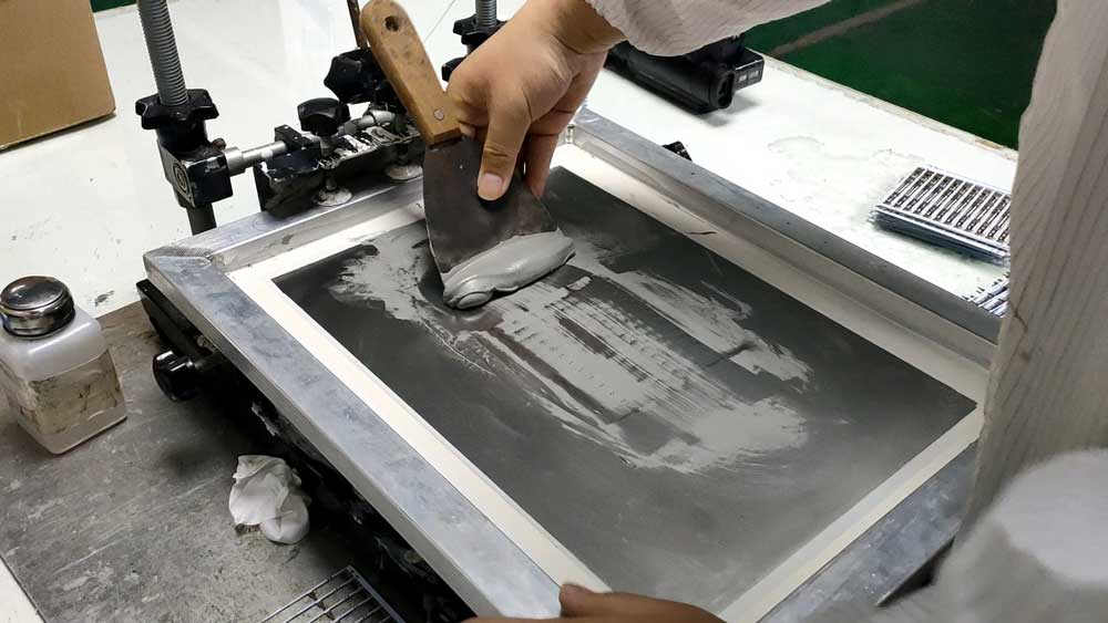
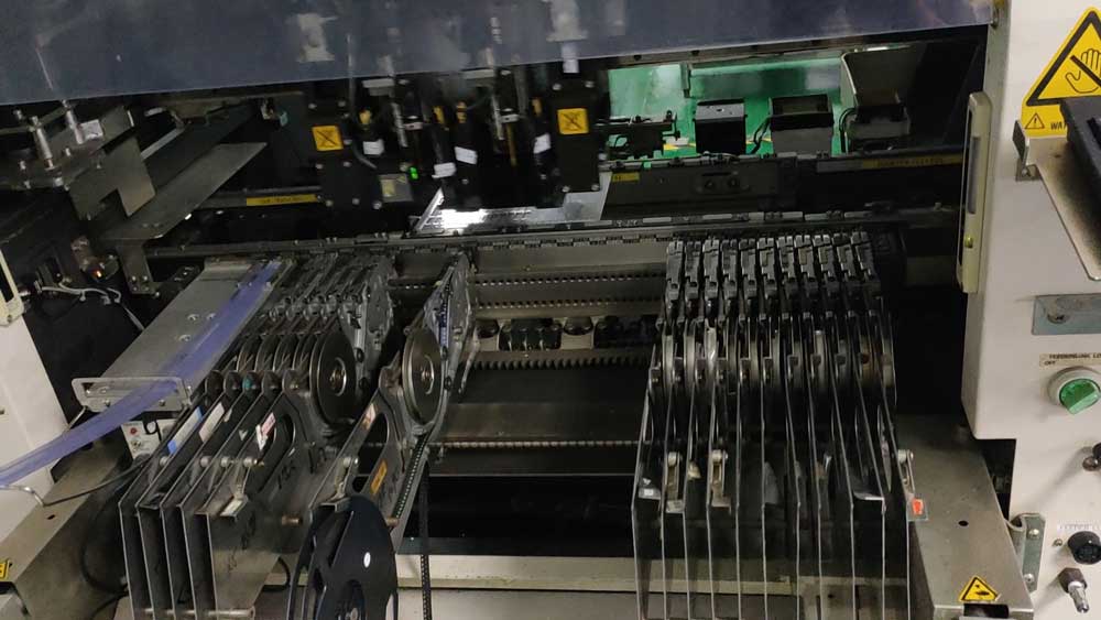
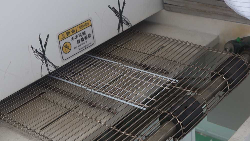
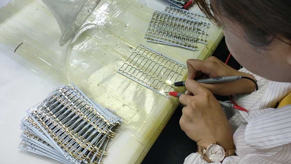
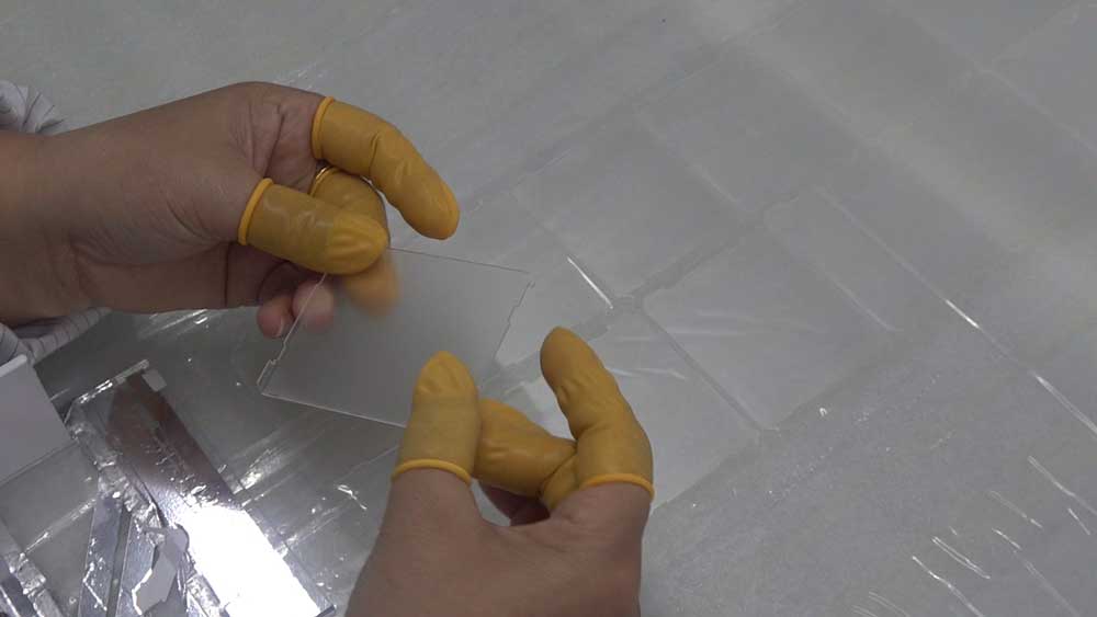
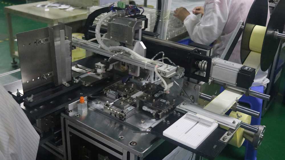
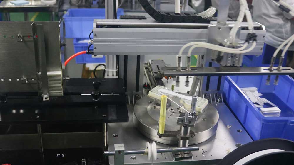
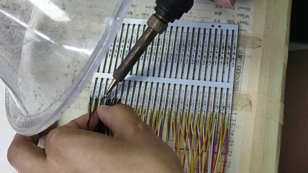
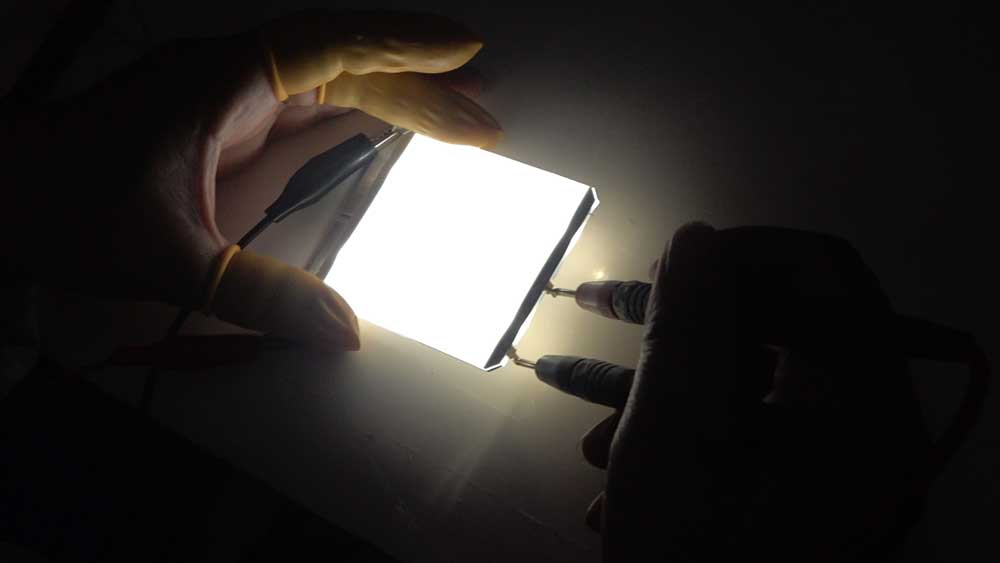
Brightness, uniformity, current, polarity, connection, dimensions and appearance should be checked against the approved sample or drawing.
| Connection Direction | Best For | Main Review Factors |
|---|---|---|
| Wire | Flexible product assembly | Length, gauge, polarity and routing |
| Wire with Connector | Serviceable OEM assembly | Connector model, pin direction and locking |
| Metal PIN | Direct PCB insertion | Pitch, length, direction and soldering |
| Hard PIN | Stable rigid connection | Mechanical support and PCB alignment |
| PCB Connection | Integrated module structure | Board position, mounting and electrical rating |
| FPC Connection | Thin or flexible structures | Tail direction, stiffener, pads and bending |
| Custom Connector | Project-specific products | Availability, pitch, mating and assembly |
Connection should be selected according to product assembly, PCB position, soldering, thickness, repairability and mass-production process.
Brightness, uniformity, thickness, LED position, Light Guide Plate, optical films, connection and product housing affect each other and must be reviewed as one structure.
Custom LCD glass and LED Backlight should be designed together when the final product requires illumination.
| Item | LED Backlight | LCD Module |
|---|---|---|
| Product Scope | Light-source component | Complete or semi-complete display module |
| Includes LCD Glass | No | Yes |
| Main Function | Provides illumination | Displays information |
| Typical Parts | LEDs, LGP, films, PCB/FPC and connection | LCD glass, polarizer, backlight, PCB, IC and connector |
| Selection Logic | Choose when only the light source is needed | Choose when the display module is required |
| Item | LED Backlight | LCD Controller Board |
|---|---|---|
| Main Function | Provides light | Drives or controls the display |
| Electrical Role | LED power and brightness | Signal conversion, timing and panel control |
| Includes Display Signal | No | Yes |
| Selection Logic | Choose for illumination | Choose for display driving and signal control |
| Item | LED Backlight | LED Display |
|---|---|---|
| Main Role | Illuminates an LCD | Creates the image with LED pixels |
| Image Formation | No | Yes |
| Used With | LCD glass or LCD module | Independent LED-display system |
| Selection Logic | Choose for LCD illumination | Choose when LEDs are the actual display pixels |
Meters, appliances, HVAC controls and fixed icon displays.
16×2, 20×4 and other text modules.
Pixel-based monochrome graphics and icons.
Custom monochrome LCD module integration.
Readable displays in controlled environments.
Timers, controls and product-status displays.
Backlit user interfaces and equipment displays.
Portable instruments, chargers and control products.
Matching old size, color, voltage, current and connection.
Segment, Character, Graphic, Dot Matrix, COB, COG or custom LCD glass.
Confirm outer size, viewing area, holes and mechanical outline.
Balance thickness, direct illumination, uniformity and cost.
Confirm color, brightness, uniformity and appearance.
Voltage, current, dimming, wire, connector, PIN, PCB or FPC.
Check readability, uniformity, light leakage, heat, fit and assembly.
The correct route depends on whether the project needs illumination only or also the LCD glass, driver electronics and complete module structure.
| Project Requirement | Recommended Product Direction |
|---|---|
| Main LCD component family | LCD Displays & Components |
| Segment, Character, Graphic or Dot Matrix LCD | Monochrome LCD Displays |
| TN, HTN, STN, FSTN or VA LCD glass | LCD Glass Panels |
| Fixed digits, icons or symbols | Segment LCD Displays |
| Fixed rows of text | Character LCD Displays |
| Pixel-based monochrome graphics | Graphic LCD Displays |
| LCD module with PCB and bonded IC | COB LCD Displays |
| Compact LCD module with IC on glass | COG LCD Displays |
| Signal conversion and display driving | LCD Controller Boards |
| Full-color TFT LCD module | TFT LCD Displays |
Send the available LCD, optical, electrical and mechanical information below. Complete data helps us evaluate feasibility, select the correct backlight structure and prepare a more accurate quotation.
Provide clear photos of the front, back, connection area and label of the original backlight. If possible, also send the old sample, LCD module, voltage/current information and photos showing how the backlight fits inside the complete product.
An LED Backlight is the light source installed behind or beside an LCD display to improve readability in indoor, low-light or controlled-lighting environments.
No. An LED Backlight only provides illumination for an LCD. An LED Display uses LEDs as the image-forming pixels.
No. It is one component of an LCD module. A complete module may also include LCD glass, polarizers, PCB, driver IC, connector and mechanical structure.
LCD glass does not emit light by itself. Transmissive and transflective LCD structures need a controlled light source for indoor or low-light readability.
Edge LED places LEDs beside the light guide plate and can support thinner modules. Bottom LED places LEDs behind the display area and uses direct illumination.
Edge LED can normally support a thinner structure when the light guide plate and film stack are properly designed.
Yes. White, blue, green, red, yellow-green and project-based color directions can be reviewed.
The color should match the LCD mode, polarizer, printed overlay, readability target and final product appearance.
Yes. Size, outline, viewing area, through-holes, thickness and special mechanical shapes can be reviewed according to the LCD and enclosure.
Yes. Through-holes and special openings can be reviewed when screws, product structures or mechanical clearances must pass through the backlight.
A backlight may include LEDs, light guide plate, diffusion film, reflective film, brightness-enhancement film, PCB or FPC, wire, connector, PIN, light-blocking film and mechanical support.
The Light Guide Plate distributes light from edge-mounted LEDs across the display area. Its pattern and design strongly affect brightness and uniformity.
Diffusion Film spreads light more evenly and helps reduce visible bright spots.
Reflective Film redirects light toward the display area and improves light utilization.
Yes. It can be reviewed when higher front brightness or better light efficiency is required.
Yes. PCB is common for stable LED mounting. FPC can be reviewed when a thinner or more flexible structure is needed.
Wire, wire with connector, metal PIN, hard PIN, PCB connection, FPC connection and custom connector directions can be reviewed.
Yes. They are commonly used with Segment, Character, Graphic, Dot Matrix, COB and COG LCD modules.
Yes. Please provide the old sample, photos, size, color, connection method, voltage, current, matched LCD and product-assembly structure.
Please provide backlight size, viewing area, matched LCD, edge or bottom LED direction, color, brightness, uniformity, thickness, holes, LED position, voltage, current, connection method, wire or FPC direction, operating temperature, application, quantity, drawing and replacement sample if available.
Send us the backlight size, lighting area, matched LCD, Edge or Bottom LED direction, color, brightness, uniformity, thickness, holes, voltage, current, connection, application, quantity and drawing.
DisplayMan will review the optical structure, LED position, Light Guide Plate, film stack, PCB or FPC, wire, connector, PIN and mechanical fit with the LCD module.
LED Backlight is the light-source component of an LCD system. It is not an LED Display and it is not an LCD Controller Board. Final performance depends on the complete optical, electrical and mechanical structure.