Quick selection guide
Should You Choose LCD or OLED?
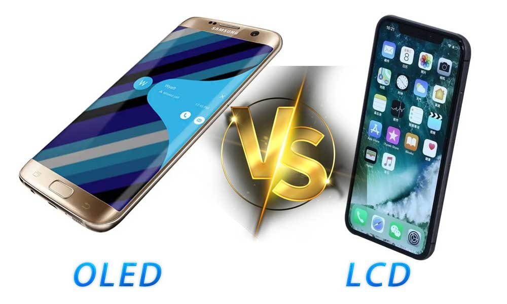
Start by evaluating LCD for a sustained bright interface, an established module platform or a high-brightness assembly. Evaluate OLED where low emitted black levels, fast emission response, thin construction or a qualified flexible form are important. Neither technology is the best choice for every OEM project.
Compare the actual content, viewing environment, operating hours, power budget, mechanical requirements and supply plan. A transparent showcase needs a separate optical assessment from an ordinary opaque screen.
DisplayMan reviews these conditions together when selecting LCD modules, OLED modules and transparent display systems.
LCD and OLED: The Fundamental Difference
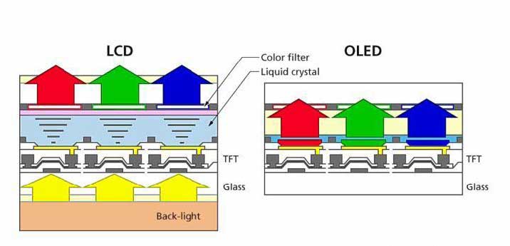
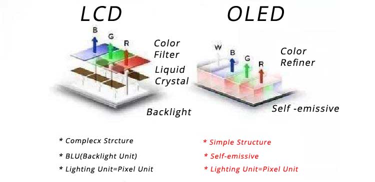
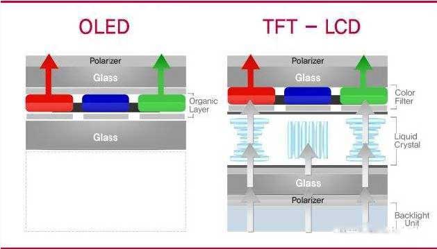
LCD uses liquid crystals to modulate light; OLED generates image light in organic light-emitting devices. A conventional transmissive LCD uses a backlight, while an OLED does not require that backlight or a liquid-crystal light-valve layer. Reflective, transflective and transparent LCD arrangements have different illumination requirements.
This difference explains important design trade-offs, but it does not determine every performance specification. Panel construction, optical layers, electronics and the application all matter. Futaba’s OLED overview describes self-emission and contrasts it with conventional backlit LCD operation. [1]
Keep the terminology precise. TFT describes active-matrix addressing; IPS, TN and VA describe liquid-crystal modes. AMOLED is an active-matrix OLED architecture, while PMOLED uses passive-matrix addressing. Flexible and transparent describe other characteristics and can overlap with those categories.
For detailed explanations, use What Is an LCD Display?, What Is TFT LCD? and OLED Manufacturing Process. The purpose here is to compare product choices rather than repeat each technology’s complete physics.
LCD vs OLED: Practical Comparison Table
The following describes common product directions, not guaranteed specifications for every module. Compare actual samples at matched luminance and under the intended viewing conditions.
| Factor | LCD direction | OLED direction | OEM decision |
|---|---|---|---|
| Image light | Usually a backlight for transmissive panels | Self-emitting pixels | Compare the complete optical system |
| Dark-room black level | Limited by the panel and illumination; local dimming can help | Non-emitting areas can achieve very low emitted luminance on conventional opaque panels | Consider ambient reflection and the use case |
| Sustained brightness | High-brightness backlights are available | Depends on panel limits, image area and drive behavior | Request sustained, content-specific results |
| Power | Often strongly influenced by backlight settings | Often strongly influenced by image content and luminance | Measure representative operating screens |
| Thickness | Includes a backlight in conventional modules | Can enable thin constructions | Check the full touch/cover/controller assembly |
| Motion | Liquid-crystal response and drive processing matter | Fast emission response is an advantage | Evaluate refresh, persistence and system latency too |
| Static content | Often a practical starting point for fixed interfaces | Differential aging must be managed | Define operating hours and content distribution |
| Curved form | Available in selected designed constructions | Flexible platforms offer further possibilities | Use qualified bend limits, not assumptions |
| Flicker | Backlight and panel behavior require checking | Emission control requires checking | Review optical waveforms and settings |
| Cost and supply | Depends on the selected module and volume | Depends on the selected module and volume | Obtain comparable assembly quotations |
Pixels, Resolution and Text Clarity
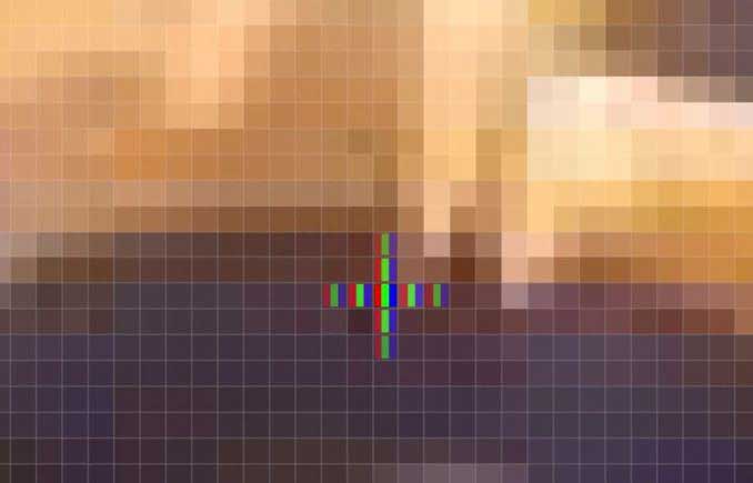
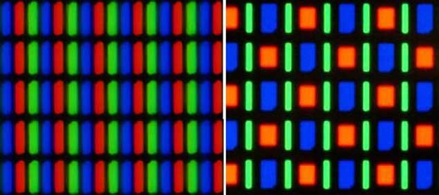
A conventional RGB display forms color by combining subpixel contributions. However, not every color panel uses the same subpixel geometry, and not every display is full color. The original pixel illustrations are teaching examples rather than a universal layout rule.
Nominal resolution states the addressed pixel count. Text clarity also depends on active area, pixel density, subpixel layout, optical stack, rendering and viewing distance. An RGB-stripe panel and a different OLED subpixel arrangement can render small text differently at the same nominal resolution.
There is no universal 20% clarity penalty for OLED. Assess the actual modules with your font sizes, line widths, icons and operating orientation. Check color fringing and edge appearance at the intended distance, rather than comparing enlarged pixel photographs alone.
A higher pixel count also increases host and interface demands. If a replacement project must retain existing electronics, compatibility can outweigh the appeal of a finer resolution.

Black Level, Contrast, Color and Backlight Leakage
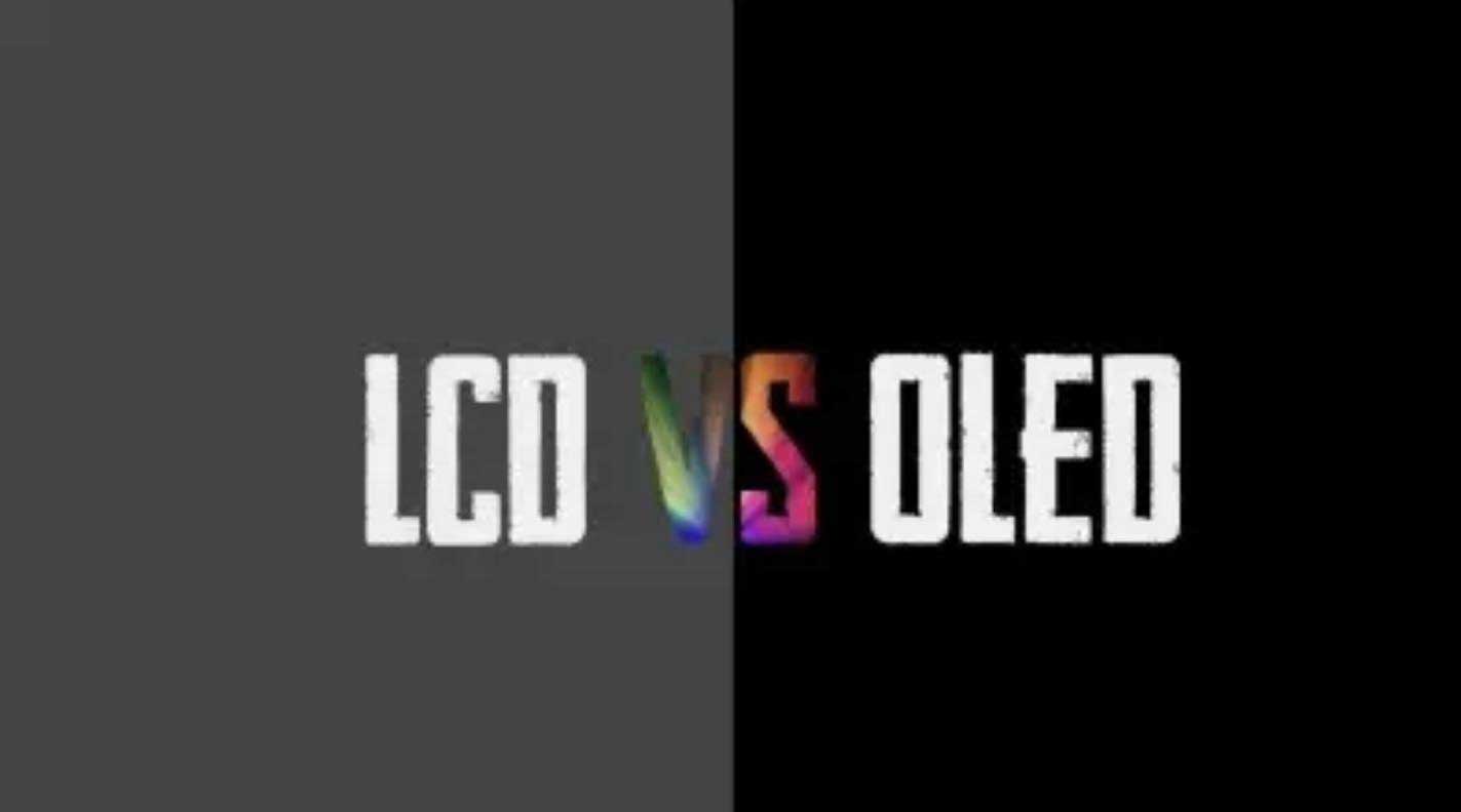
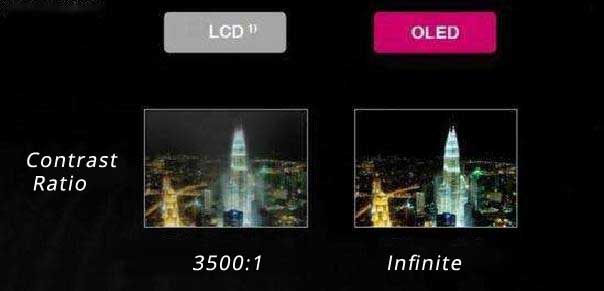
On an ordinary opaque OLED, reducing or stopping emission in dark regions supports very low emitted black levels. A conventional LCD’s optical stack does not block all backlight perfectly. This can give OLED an advantage for dark content in controlled lighting, but the original “fatal defect” description is misleading.
Ambient reflection changes the apparent black level of both technologies. Color quality also depends on gamut, white point, calibration, viewing angle and processing. OLED is not automatically accurate, and a well-selected LCD is not inherently washed out.
LCD illumination architectures vary. Local dimming can control backlight zones, although a zone is not the same as an independently emissive OLED pixel. Sony’s backlighting overview distinguishes edge-lit, direct-lit and full-array local-dimming systems. [2]
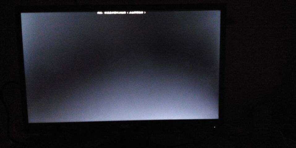
Backlight leakage and uniformity should be evaluated under agreed viewing conditions. Mechanical stress, optical design and assembly influence the result; an exaggerated dark-room photograph is not a complete acceptance specification. Inspect the final module with representative content, not just a black image at an arbitrarily long camera exposure.
Transparent displays require a separate interpretation. A non-emitting transparent OLED region still shows the background, so ordinary opaque-OLED “perfect black” arguments do not transfer directly to a see-through installation.

Brightness and Readability in Strong Ambient Light
For an indoor device, brightness should match the viewing environment, front-surface reflection and power budget. For window-facing or outdoor use, sustained luminance, sunlight loading, cooling, protective materials and enclosure design become important together.
High Brightness TFT LCD Displays are a useful direction to investigate when the project needs a bright interface or display assembly. The suitability of the exact module still depends on temperature, operating schedule and optical integration.
OLED specifications must also be read with their conditions. A peak value for a small image area or brief operating state is not necessarily the brightness available for a full white screen throughout a working day. Ask which content, duration, temperature and control mode produced the quoted value.
Do not select a technology from nits alone. Measure front-of-assembly readability through the intended touch layer and cover glass. Anti-reflection treatment, glare, viewing orientation and the background scene can change the outcome substantially.
Power Consumption: Compare the Actual Content
OLED can be efficient for dark interfaces with limited illuminated area because pixels emit where required. Futaba specifically relates this advantage to low lighting-rate content. It is not evidence that OLED always uses less power than LCD. [1]
An OLED displaying a predominantly bright image has a different power requirement from one displaying sparse text on black. A conventional LCD’s backlight power may change much less with image content, though local dimming and other controls can alter that behavior.
For a fair comparison, match the useful luminance and content rather than slider percentage. Include panel electronics, controller conversion losses, backlight drive, touch electronics and any necessary cooling when they are part of the purchased system.
| Test screen | Why to include it | What to record |
|---|---|---|
| Actual idle/status UI | Represents the time spent waiting or monitoring | Average system power and readability |
| Typical working screen | Represents normal interaction | Power, brightness and temperature |
| Predominantly white screen | Checks a demanding bright-content state | Sustained luminance and any limiting behavior |
| Video or changing graphics | Represents dynamic use | Average and peak demand over a defined sequence |
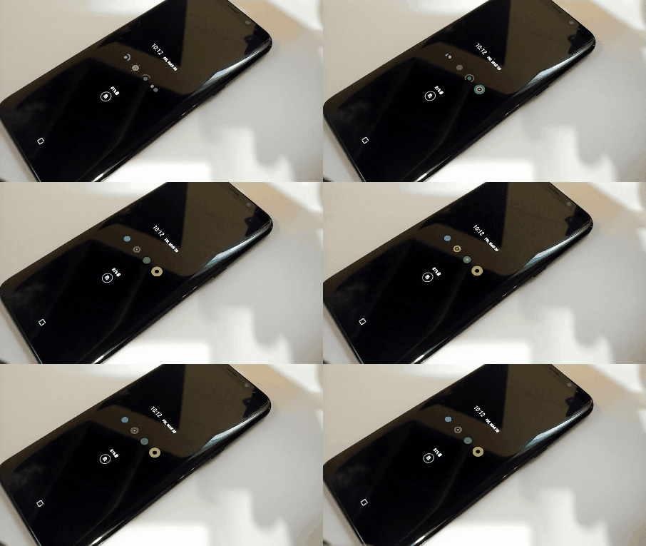
An always-on display feature does not make the entire device consume zero power. It also creates a content-management and lifetime question if the same elements remain visible for long periods.
Static Interfaces, Burn-In and Lifetime
OLED differential aging can leave persistent nonuniformity associated with the history of pixel use. Brightness, current, temperature, content and operating duration affect the assessment. There is no general guarantee that a particular slider percentage prevents burn-in for three years.
LCD products also age and can show image retention or uniformity changes. Backlight deterioration, polarizers, bonding, electronics and environmental stress all contribute to the complete product’s service life. “LCD is inorganic” is not an adequate reliability explanation: an LCD assembly contains several material systems.
For fixed industrial interfaces, continuous dashboards or repeated logos, an LCD is often worth evaluating early. This is a project-selection judgment, not proof that an OLED can never serve such an application.
For an OLED installation, review brightness management, content layout, idle behavior and the manufacturer’s supported compensation or maintenance functions. Do not promise that software can eliminate all aging. The OLED Burn-In guide explains the issue in more detail.
Compare lifetime figures only when the definition and test conditions are known. Define the acceptable end-of-life behavior, planned operating hours and service strategy. Warranty terms must come from the actual quotation or agreement, not a generic brand anecdote.
Flicker, Response Time and Refresh Rate
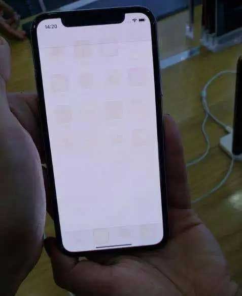
OLED can offer fast emission response, but that does not establish zero system latency or eliminate every motion artifact. Refresh rate, sample-and-hold behavior, processing and content also affect the visible result. LCD response varies with the transition, temperature and drive implementation.
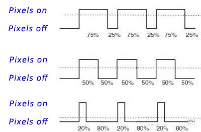
Brightness control is a separate issue. An LCD backlight can use PWM; an OLED can use timing-based, current-based or hybrid control depending on the product. Neither technology label proves modulation-free operation.
Do not infer a frequency from a brightness-slider setting, or assume that the OLED frequency falls whenever brightness is reduced. Camera bands can reveal an interaction with the camera’s sampling, but are not a calibrated comfort assessment.
For the full measurement approach, see OLED Flicker: PWM, DC Dimming and OEM Testing. The same guide explains why subjective discomfort and eye injury are different questions; this comparison does not classify either technology as medically safe or harmful.
If temporal behavior matters to the application, include optical waveform captures across the intended dimming range and relevant operating modes in the sample plan.
Thickness, Curvature and Mechanical Integration
Eliminating a conventional backlight can help OLED achieve a thin optical assembly. The finished product still includes encapsulation, interconnections, supporting structures and possibly touch, cover glass and a controller enclosure. Compare mechanical drawings for the complete assembly.
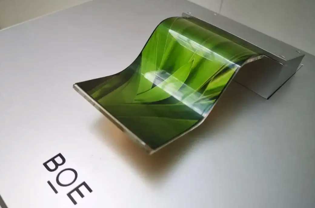
A flexible OLED is not a sheet that can be folded freely like paper. The approved bend radius, bend direction, support, cable transition and cycle requirement determine how it may be used. DisplayMan’s Flexible OLED Displays direction supports bendable or curvable integration; repeated folding is not assumed.
Selected LCD constructions can also be curved. That does not mean a standard flat module may be bent during assembly. Confirm the supplied construction and permitted loads with the supplier.
For both technologies, avoid pressure on unsupported glass or active regions and provide appropriate strain relief. A panel that survives on a bench can fail after installation if the enclosure imposes stress or traps heat.
Transparent LCD vs Transparent OLED: A Separate Project Choice
A transparent LCD normally relies on a planned illumination environment behind the panel. It can be useful for a product cabinet where lighting and background can be designed together. Panel dimensions, cabinet depth, displayed objects and illumination affect the complete result.
Transparent OLED emits its own image light and can support a slim see-through arrangement. Background brightness still affects the perceived image. A black part of the content does not create an opaque black mask over the object behind it. LG’s transparent-OLED product information confirms the distinct backlight-free structure and product-specific transmission specifications. [3]
Do not transfer an ordinary LCD-versus-OLED contrast chart directly to these systems. Compare the actual transparent installation under the intended background and lighting.
| Project question | Transparent LCD direction | Transparent OLED direction |
|---|---|---|
| Where does image illumination come from? | Planned rear/product lighting | Self-emitting image pixels |
| What needs mechanical space? | Panel plus lighting and cabinet arrangement | Panel, supporting structure and electronics |
| What affects readability? | Lighting, objects, background and content | Ambient light, background and emitted content |
| What establishes the budget? | Complete cabinet, illumination and integration | Panel, electronics, mounting and integration |
Explore Transparent LCD Displays and Transparent OLED Displays. For the detailed cabinet decision, use Transparent Display Cabinet Engineering.
If the question is specifically transparent Micro LED versus transparent OLED, use the separate transparent display comparison. That is a different selection problem from a conventional LCD-versus-OLED module comparison.
OEM Cost, Customization and Supply Planning
A panel-only price is not a complete system quotation. Compare the module, controller, cables, power supply, touch, cover glass, bonding, mounting, testing and packaging within the same supply boundary.
A standard panel with customized supporting parts can be more practical than a new panel design. Changing an FPC, glass outline or enclosure does not automatically change the active pixel area. New panel development needs separate feasibility, tooling, MOQ and qualification review.
Ask which requirements are mandatory and which can follow an available platform. Diagonal alone is insufficient: active area, outline, connector location and thickness all affect mechanical fit. Image interface, power sequence, initialization and firmware determine electrical compatibility.
Supply continuity also deserves attention. Confirm the exact part revision, change-notification arrangements and the process for evaluating alternatives. A visually similar replacement may require different electronics or software.
DisplayMan can help review TFT LCD modules, AMOLED displays, PMOLED displays and transparent systems against the project requirements. Customization scope, quantity and development cost should be agreed before treating an option as production-ready.
How to Compare Samples Before Approval
Use the same representative content, matched useful luminance and the intended viewing distance. Retain the configuration information so that production samples can be checked against the same conditions.
| Check | Evidence to retain | Decision supported |
|---|---|---|
| Optical quality | Gray patterns, text, real UI and viewing-angle assessment | Legibility, color and uniformity |
| Ambient readability | Test through final front optics in representative light | Suitability for the installation |
| Sustained operation | Brightness, power and thermal behavior over an agreed period | Whether short demonstrations represent daily use |
| Electrical compatibility | Host setup, initialization, pinout and power sequence | Integration feasibility |
| Temporal behavior | Relevant waveforms and camera tests where needed | Dimming and recording requirements |
| Static-content operation | Content schedule and supplier-supported measures | Aging and service planning |
| Mechanics and supply | Approved drawing, assembly revision and change process | Repeatable production and maintenance |
A useful RFQ includes application, screen content, size, resolution, interface, viewing environment, temperature range, operating schedule, touch requirements, quantity and target schedule. Add drawings and a working sample for a legacy replacement project.
Do not select the sample solely because its demonstration video looks more saturated. Freeze the acceptance criteria that matter to the finished product, then approve the assembly against those criteria.
Frequently Asked Questions
Is OLED always better than LCD?
No. OLED can be attractive for dark-room black levels, fast emission response or particular thin and flexible constructions. LCD can be a practical choice for sustained bright interfaces, high-brightness assemblies and established module platforms. Compare actual products against the use case.
Does OLED always save power?
No. OLED consumption depends strongly on emitted content and luminance. Compare the complete assembly using representative screens at matched brightness.
Is an LED-backlit LCD an OLED?
No. Its LEDs illuminate a liquid-crystal panel. OLED creates image light in organic light-emitting devices. Direct-view LED displays are another category.
Does every OLED fold?
No. Many OLED products are rigid. Flexible products still require an approved mechanical design and must not be folded beyond their qualified limits.
Can LCD be suitable for continuous operation?
Yes, with a suitable rated module and complete system design. Operating hours, temperature, backlight drive and service requirements must be checked for the exact product.
Is transparent OLED guaranteed to have opaque black areas?
No. A non-emitting area can transmit the background. Evaluate transparency, background lighting and content together instead of assuming conventional opaque-OLED black behavior.
From comparison to product
Explore Related Display Products
Review the product direction, then confirm the exact panel, electronics and integration requirements.
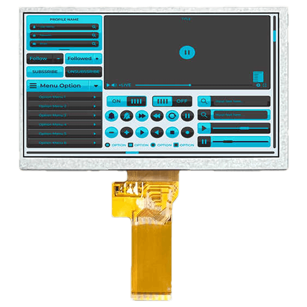
TFT LCD Displays
Explore color modules for OEM interfaces, with mechanical, electrical and optical requirements reviewed together.
Explore product options →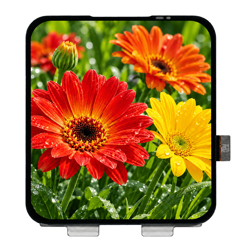
AMOLED Displays
Review full-color module options for detailed interfaces, graphics and OEM products.
Explore product options →
Transparent OLED Displays
Explore see-through displays for showcases, signage and engineered commercial systems.
Explore product options →Project review
Choose a Display Around Your Project Requirements
Send your application, typical screen content, dimensions, interface, operating schedule, lighting conditions and quantity. DisplayMan can review LCD, OLED and transparent display directions against the requirements of the complete assembly.
Prefer to open the enquiry form here?
Technical References and Further Reading
- Futaba: OLED structure and content-dependent power examples
- Sony: Edge-lit, direct-lit and local-dimming backlight systems
- LG: Transparent OLED structure and product-specific specifications
General principles and selection questions are not substitute specifications for an individual panel. Original article illustrations are retained with limitations; compare the approved module and final assembly under agreed test conditions.