As we all know, nothing can stop the development of technology. It is an inevitable trend that wearable technology will become the wave of the future since Apple and Google have separately launched their wearable watches.
One of the components the wearable watch needs is LCD screen. I have been receiving RFQs of round LCD display module since last year. Let me introduce you the 3 main ways that we make custom round display module.
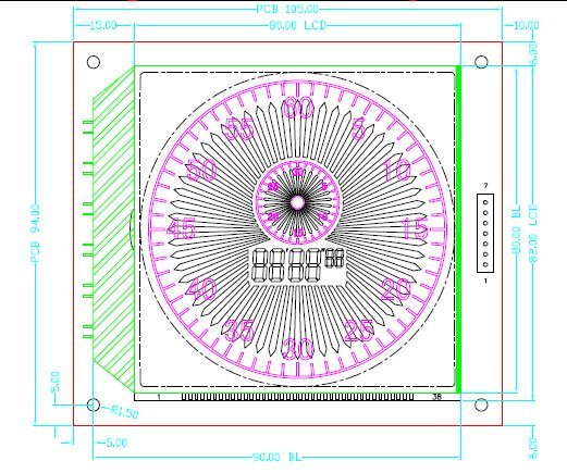
1. Plan A: Rectangle LCD.
It is a very common monochrome LCD screen. The pink graphic we see is the silk painting which is printed on the ITO glass. The outer clock is counting the seconds, so the black needle makes a complete turn in 60 seconds; and the inner clock is counting the minutes, so the black needle makes a complete turn in 30 minutes. In the middle of LCD screen, it is a typical 7-segment digital that could count minutes, seconds and 1/100th a second.
The LCD module includes LCD screen, IC, LED backlight (not necessary) and PCB (not necessary). The view area is only 77.0*77.0 mm, the LCD screen is 80.0*82.0 mm, but the whole COB LCD module is 94*105mm.
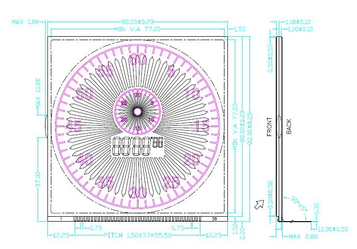
LED backlight has to be larger than LCD screen, otherwise, LCD screen can’t be lighted up.
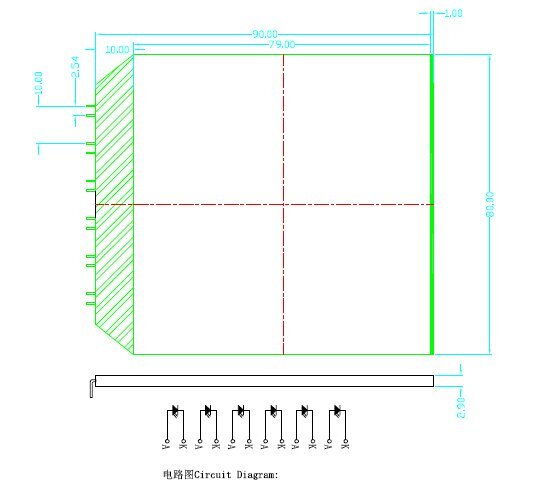
We use 6 DIP LEDs as the light source of LED backlight, and it needs 10 mm(8 mm at least) light shade area, check the green area of the picture above, that is why it is so big. The PCB is much bigger because there are 4 pieces of radius 1.5 mm screws to fasten the PCB and other devices together.If we put a plastic shell in front of it, it becomes a round LCD. The advantage of this methodology is that it is easiest to make, cheapest, and most stable. But the disadvantage is that the whole size of LCD module is too big. We can find a way to make it much smaller.
2. Plan B: Round LCD.
The outer size of PCB is only 88.0*85.5 mm and the size of LCD is 86*83.5 mm.
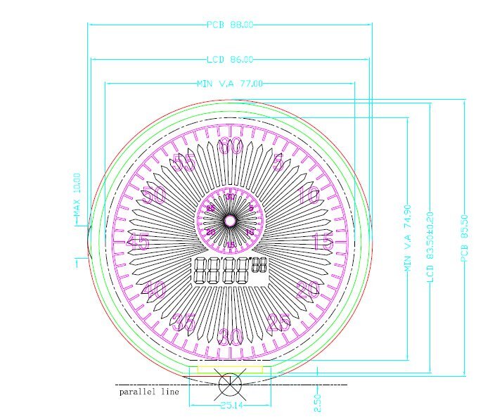
How can we make it so small? First, we confirm the view area 77*77 mm. Second, expand it 1.5 mm which is the minimum distance between the edge of LCD screen and view area. Third, expand it by 2.0 mm which is the distance between upper ITO glass and lower ITO glass. I marked the upper and lower ITO glasses with green lines.Fourth, expand it 1.0 mm which is the width and height of walls. Fifth, if I didn’t make a mistake, the LCD screen, LED backlight and PCB should be all round. As we know, LED backlight and PCB can be round, but not LCD screen. If LCD screen is round, what kind of connection should be used? Metal pin, zebra or conductive rubber strip can’t be installed in the round edge. Find the middle point at the bottom of LCD screen, draw a parallel line and move it up 2.5 mm, and we cut it along with the line, that is the edge of PCB. Move it up 1.0 mm and 2.0 mm, that is the edge of LCD screen. Move it up to 1.5 mm, that is the view area.
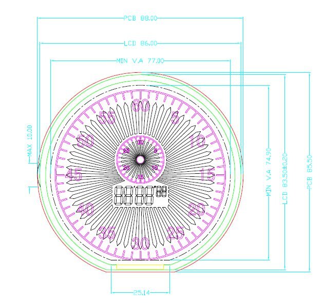
We finally get the parallel edge where conductive rubber strip or zebra can be installed. We can see that the parallel edge of LCD is only 25 mm. But how many segments do we have? 60 seconds segments + 30 minutes segments + 6*typical 7-segment digitals=132 segments. Duty is 1/4, 132/4+4=37 pieces of legs. There are 4 commonly used types of pitches for PINs: 1.27 mm, 1.5 mm, 2.0 mm, and 2.54 mm. There is no enough space (37*1.27=46.99 mm) to install PINs. But the minimum pitch of conductive rubber strip or zebra is 0.3 mm or 0.4 mm, therefore there is enough space (37*0.4=14.8 mm).
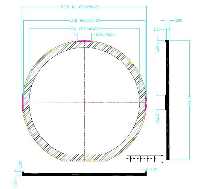
You may notice that LED backlight and PCB are the same sizes. But how can we fasten the LED backlight and PCB together? We need a plastic shell with a hole to hold all these pieces tight. Besides, there are 3 hooks in the LED backlight to hold the LCD screen. The disadvantage of this design is that it is expensive because it needs two special molds: one round LCD screen with a small semi-circle missing and a dedicated light guide plate which is to make LED backlight. And I don’t think it is very stable because all the parts are only held by the plastic shell (or cover).
Here we check the third way.
3. Plan C: Octagonal LCD.
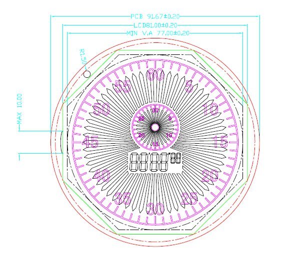
First, we make a smaller octagon cover exactly the same size as the view area of LCD screen.
Second, we extend it 2.0 mm (1.5 mm at least), see the green line in the picture above, and we get a bigger octagon which is the area of the LCD screen.
Third, make a small circle that can cover exactly the same size as the whole LCD screen.
Fourth, extend it 2.0 mm, see the red line in the picture above, and get a bigger circle which is the area of PCB.
Or we make the octagon view area into a hexagon. No matter it is an octagon or hexagon, we can get the same result.
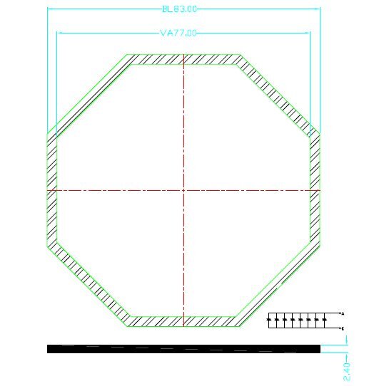
We can see that LED backlight (83.0*83.0 mm) is a little bigger than LCD screen (81.0*81.0 mm) and view area of them is exactly the same. Although we can’t fasten the LED backlight and the LCD screen together because there is no hook or screw, but there is enough space in the PCB to install the screws which can hold onto other objects. This plan C needs a plastic shell or cover as big as plan B to hold all of them together. Here I figure out some pros and cons of these plans.
| price | space | technology requirements | stylish | stable | |
| Plan A | cheapest | largest | simple | bad | really good |
| Plan B | expensive | small | most difficult | good | good |
| Plan C | cheaper | larger | more difficult | good | good |
In my opinion, there is no good or bad in these plans. But there is the most suitable one for you. Let me know if you have any questions about this.

