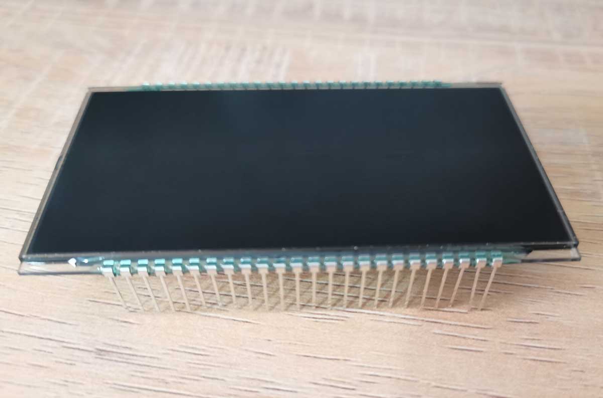
PIN connection is the most widely used connection because it is very steady.
Unfortunately, not everyone is an expert at soldering. Every now and then, we can hear customers complaining about the high failure rate after the PINs were soldered on PCB. And I was always wondering if they did the soldering properly. More often than not, it’s the soldering problem. It’s not the quality problem of LCD screen itself. We feel it is our obligation to do some tests to help those who lack experience.
In order to test the impact of the soldering temperature, we deliberately made it 350 degrees Celsius far higher than the normal. The soldering iron head was placed at the distance of 4.0 mm from bottom of LCD screen.
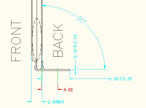
It only took about 4.0 seconds to melt the glue before it bubbled. It would cool down in a few seconds after the soldering iron head was removed and then it solidified slowly and shrank when it was completely cooled.
One interesting idea was that we located the PIN which was responsible for the missing segments of LCD screen and re-soldered it with overheated temperature. Pulled the PIN down a little, which would make it temperately connect in normal again. We could see it displaying the whole diagram for a while. When we were glad that we fixed the LCD screen, the old problem repeated again. It was easy to understand because the overheated temperature damaged the glue and turned the chemical composition into something else. Now the LCD screen was completely damaged and was unrepairable.

Let us try another experiment. We soldered the perfectly normal LCD screen with overheated temperature. It was as sure as the sun comes from the east that the old missing segment problem recurred. I am going to remind everyone here don’t ever solder the PINs with overheated temperature because it will definitely cause the missing segment problem.
Let us hit the PINs with overheated temperature while we don’t use the UV glue to fasten the positions of the PINs. Wait. Is it possible not to use UV glue? Of course, it isn’t. It is never able to fasten the PINs without UV glue. This was just an experiment to explain what would happen in a hypothetical situation. Now we continued the experiment. We put a 350 degree Celsius soldering iron head directly on PIN for 10 seconds and more until the polarizer turned yellow. To our surprise, the LCD screen was working perfectly fine. Now we could conclude that it was UV glue which was overheated that caused the missing segments and other problems. But we can’t make a LCD screen without it.
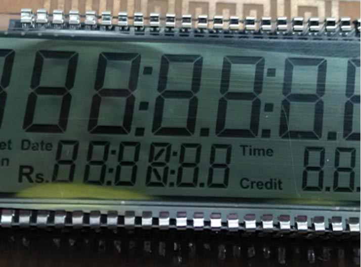
Let us test the dark green and colorless UV glue and see if the color has any effect under the overheated temperature. When we used colorless UV glue, a 350 degree Celsius soldering iron head was put directly on PIN and at the distance of 4.0 mm away from the bottom of LCD screen. It took about 6 to 8 seconds to see the bubbles. While it only took 4.0 seconds to see the bubbles when we adopted the dark green UV glue. Additionally, the colorless UV glue was harder than the dark green UV glue when it was dried. We can assume that the colorless UV glue is better and it is more high-temperature resistant.
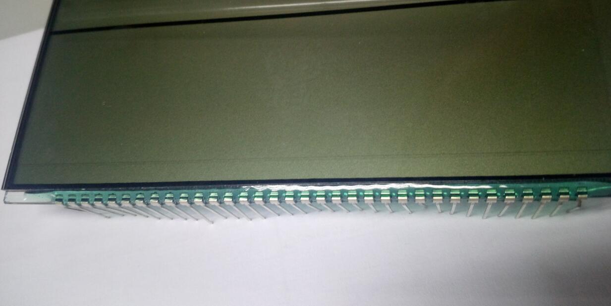
Finally, we make a few suggestions for welding LCD PINs.
1. The distance from the soldering iron head to the bottom of LCD screen should be at least 4.0 mm and the temperature should be below 260 degrees Celsius. The time should be less than 4 seconds for the soldering iron head on PINs to avoid making the glue bubble.
2. The soldering iron head should contact two adjacent PINs at the same time and make the heat transfer more evenly. It should form 30 degree angle with PINs because this will make contacting area larger and heat transfer faster. It will be a perfect heating condition if we can make the two adjacent PINs reach the same temperature at the same time.
3. It is forbidden to let the PINs bear any pressure while we are welding the PINs. In order to prevent the displacing of the PINs because of the pressure from outside, it is best if we lay the front surface of LCD screen flat on a table.
4. It shouldn’t solder more than 3 times and wait at least 5 minutes before your next try.
5. The two PINs on the two ends bear a greater tension and they are more likely to be damaged because of the pressure. We strongly suggest that we add two more extra PINs that are not connected on two ends to lighten the burden if the products have a high-quality requirement.

