
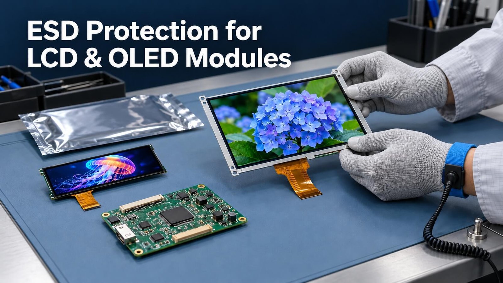
DisplayMan Engineering Guide · Quick Answer
How Do You Protect LCD and OLED Modules from ESD?
Prepare a verified ESD workstation before unpacking, use the approved personnel-grounding method, avoid exposed contacts, follow the module’s power-off connection procedure and keep the display in suitable protective packaging when it leaves the workstation.
LCD and OLED modules, touch controllers and display driver boards can all contain sensitive electronics. Gloves or humidity alone are not a complete protection method. For a DisplayMan assembly, use the instructions for the exact module, controller and cable combination.
If a screen stops working, do not assume ESD is the cause. Check power, pinout, cable seating, firmware and mechanical damage under a controlled troubleshooting process.
Why ESD Protection Matters for Display Modules
A display can leave the supplier working correctly and develop problems during incoming inspection, assembly or testing. Electrostatic discharge is one possible cause—but not the only one. Wrong supply voltage, a reversed cable, connector damage and mechanical stress can produce similar symptoms.
For an OEM project, the useful question is not simply “How do I avoid static electricity?” It is “How do I protect the display, driver board and touch electronics through every handling step?” This guide applies that question to DisplayMan’s LCD, OLED and integrated display products.
The recommendations below are a starting point for a documented process. The approved module datasheet, assembly instructions and your site’s ESD control plan determine the exact limits and procedures.
What Is Electrostatic Discharge?
ESD is a rapid transfer of charge between objects at different electrical potentials. Contact and separation—such as removing packaging or peeling a film—can generate charge. Discharge can occur through direct contact or across a small gap. A visible spark is not required. [1]
A familiar shock from a doorknob helps explain the phenomenon, but it is not a useful pass/fail test for display handling. If you cannot feel a discharge, that does not establish that a component is safe. Sensitivity depends on the device and the test model; there is no single damage voltage that applies to every LCD or OLED module.
Static control aims to reduce charge generation, manage differences in potential and prevent damaging discharge paths. It is a coordinated process, rather than a single accessory worn at the bench. [2]
Which Display Products and Parts Need Protection?
The most relevant handling points are often exposed connectors and electronics, rather than the front image surface alone. The following table identifies practical review points; it does not rank the ESD sensitivity of different technologies.
| Product or assembly | Parts to review | Typical customer operation |
|---|---|---|
| TFT LCD modules | Driver ICs, FPC contacts, panel connectors and timing electronics where fitted | Unpacking, connecting a host board, first power-on |
| Monochrome LCD modules | Driver ICs and exposed PCB or connector contacts; bare glass needs its own handling instructions | PCB assembly, contact alignment, functional inspection |
| OLED modules | Driver electronics, FPC and board connectors | Prototype integration, cable changes and testing |
| Touch display assemblies | Touch-controller board, flex cable and exposed connections | Touch integration and controller setup |
| LCD controller boards | Interface components, power circuitry, connectors and test points | Panel matching, firmware loading and bench testing |
| Transparent display systems | Panel electronics, external control box, interconnects and service interfaces | Cabinet installation, cable routing and maintenance |
Explore TFT LCD displays, OLED displays and LCD controller boards when selecting the hardware. Confirm the handling instructions for the exact assembly you purchase.
Step 1: Prepare the Workstation Before Opening the Package
Prepare the bench first, then unpack the display. Opening a protected module on an ordinary desk and carrying it to an ESD workstation afterwards leaves an avoidable handling gap.
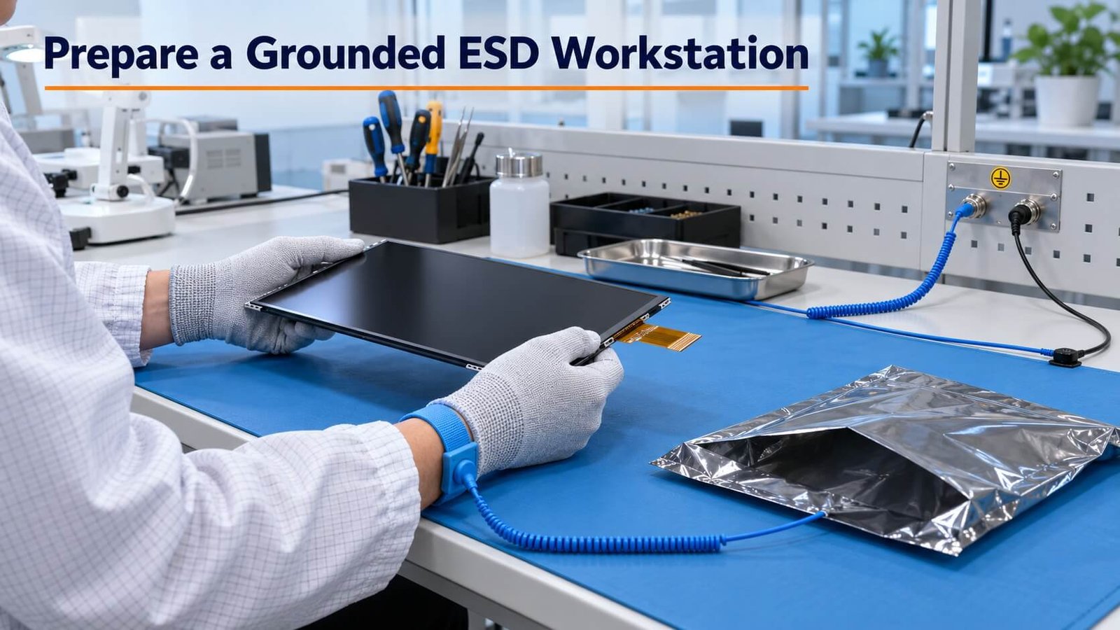
Four ESD Control Items for a Display-Module Workstation
The featured illustration brings four control items together. Use the list below to understand their different roles when handling LCD modules, OLED modules and controller boards. These items complement one another; their suitability and performance must be verified under the site’s ESD control plan.
1. ESD-Safe Gloves and Work Garments
ESD-safe gloves can help control charging during handling while reducing fingerprints and contamination. Choose gloves with documented electrical properties and a clean, non-abrasive surface suitable for the module. Ordinary cotton, latex or nitrile gloves should not automatically be treated as ESD-safe. Keep gloves clean and replace damaged or contaminated pairs.
ESD control garments help manage charge associated with clothing near exposed electronics. Use an approved garment system, wear it as instructed and check its condition after cleaning. A garment’s appearance does not establish its electrical performance. Gloves and garments do not automatically replace the specified personnel-grounding method.
2. Wrist Strap and Grounding Lead
A correctly fitted wrist strap provides a controlled path for personnel charge through its approved grounding system. Keep the wristband in the contact arrangement specified by its manufacturer—normally direct skin contact—and connect its lead to the verified common-point connection. Check the complete wristband-and-lead system according to the site procedure; a disconnected or broken lead defeats its purpose. Do not bypass the safety components of an approved grounding cord.
3. Static-Dissipative Work Mat
A suitable work mat provides a controlled surface for handling the assembly. Connect it as specified in the ESD plan and verify its performance, including the grounding connection. Keep it clean using approved methods. Avoid placing an energized PCB directly on a surface that could short exposed conductors; use the approved supports or fixture. The mat is not simply a cushion and does not work by storing all static charge indefinitely.
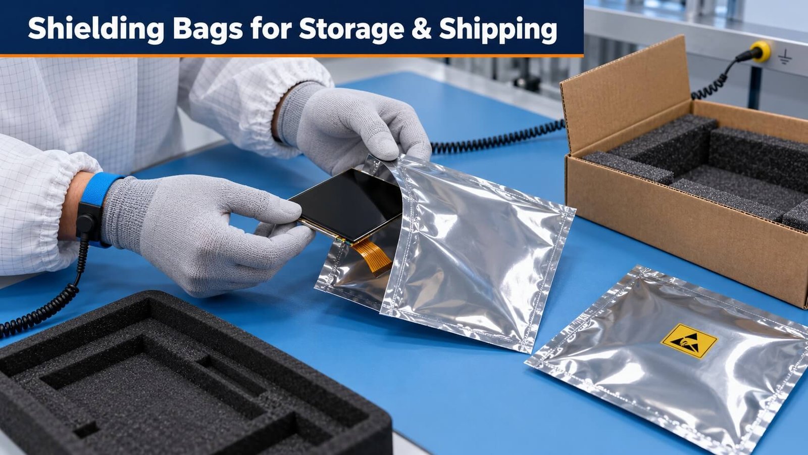
4. Static-Shielding Bag
A suitable static-shielding bag helps protect a sensitive module while it is stored or transported outside the protected area. Many shielding bags have a silver or metallized appearance, but color alone does not prove shielding performance. Select documented packaging, close it as instructed and inspect it for punctures, damaged seams or wear. A low-charging bag without shielding is not an equivalent substitute where discharge shielding is required.
Use appropriate trays and cushioning to protect glass, FPCs and connectors as well. Do not use the outside of a shielding bag as an improvised powered test surface. Open and repack the module at the prepared ESD workstation.
Practical check: before opening the display package, confirm suitable gloves and garments, a verified personnel-grounding arrangement, the prepared work surface and the correct packaging for the next handling stage. The site procedure determines any additional controls, such as ionization. See control principles [2] and workstation and material guidance [3].
Personnel, Worksurface and Tools
Use the personnel-grounding method and dissipative work surface specified by the site’s ESD plan. Their connections and performance need verification: a wrist strap that is disconnected or a mat with a broken lead cannot provide its intended function. An approved footwear-and-flooring system must work as a system; an “ESD floor” alone is not sufficient. [3]
Use a designated, verified ESD common-point connection. Have the grounding arrangement checked by a qualified person. Do not improvise a connection to a mains neutral conductor, an unknown metal frame or an unverified earth point. ESD controls do not replace electrical safety procedures, especially around exposed hazardous voltages.
Review fixtures, soldering equipment and hand tools for suitability. Keep ordinary plastic bags, foam, tape and loose packaging away from exposed modules where they are unnecessary. Gloves may help with cleanliness, but they do not automatically ground the operator.
Humidity, Garments and Ionization
Humidity can affect charge generation, but a humidifier is not a substitute for verified ESD controls. Select environmental limits around the product, materials and approved process; avoid condensation and do not impose a universal 40–70% range on every display project. [4]
For insulating materials that must remain in the process, such as some films and plastic fixtures, grounding alone may not remove charge effectively. Evaluate ionization where required, and verify the equipment rather than assuming airflow is sufficient. Garments likewise need to be selected as part of the control program. [2][3]
Step 2: Unpack and Handle the Display Correctly
Check the shipping carton and inner packaging for impact, moisture or damage before opening. Record the part number and any visible concern so that a later fault can be traced to the correct unit and handling stage.
- Bring the protected package to the prepared workstation.
- Open it using the approved process, keeping loose packing material away from the handling area.
- Support the module at the locations permitted by its mechanical instructions. Avoid touching exposed electrical contacts.
- Place it on an approved support or tray; do not leave glass, FPCs or components unsupported.
- Keep the original protective materials for storage or return shipment if they remain serviceable.
Do not lift a display by its FPC or backlight cable. Do not press on the image area, driver bonding region or exposed components. Mechanical damage is a separate risk that a good ESD workstation cannot prevent. Display handling guidance also cautions against sharp folding or excessive force on cables. [5]
Removing Protective Film
Film removal deserves its own assembly instruction. Contact and separation can generate charge, while pulling on a film can also stress a thin panel. Remove only the film identified for removal, at the approved production stage, with the panel properly supported. Assess the need for ionization and verify that film removal does not disturb cables, edge seals or bonded parts. [1][2]
Step 3: Connect the FPC, Panel Cable and Controller Board
A connector that fits mechanically is not proof of electrical compatibility. Before first connection, confirm the panel part number, board configuration, pin assignment, supply rails, backlight requirements and cable orientation.
For internal panel, FPC and backlight connections, use the approved power-off assembly procedure. Do not hot-plug an internal connection unless the exact interface and assembly are expressly designed and approved for it. Disconnect the relevant supplies and allow stored energy to discharge as instructed; a dark image does not prove that every rail is off.
- Check the FPC contact side and connector locking mechanism.
- Seat the cable squarely and close the latch without forcing it.
- Confirm pin 1 and the complete cable pinout; do not rely on wire colors alone.
- Provide strain relief and the specified bending clearance.
- Keep cables away from sharp edges, moving parts and hot surfaces.
Follow the selected module’s power and signal sequencing requirements. Display manufacturers may specify restrictions on applying signals while logic power is absent. Such requirements are model-specific, so do not invent one universal connection order for LCD, OLED and every host interface. [5]
For DisplayMan controller-board projects, review the display, board and cable as a matched set. The LCD controller board product page explains the available integration directions.
Step 4: Carry Out a Controlled First Power-On
A useful first-power-on record separates electrical setup problems from faults introduced later. Before energizing, check the approved supply settings, wiring, board firmware or panel profile and connector seating.
Use the test fixture and power source specified for the assembly. Where a current limit is appropriate, use the approved value rather than an arbitrary setting. Check for unintended shorts to the work surface or mounting fixture before powering an exposed board.
Record the baseline image and operating state, then perform the agreed checks:
- Image display, initialization and any abnormal lines or flicker.
- Backlight operation for LCD, or emissive operation for OLED.
- Touch response and communication where fitted.
- Supply readings and temperatures where the test plan requires them.
- Part numbers, board revision, cable identification and test settings.
If behavior becomes abnormal, stop and investigate before repeatedly swapping live connections. For sample evaluations, change one variable at a time so the result remains useful.
Transparent LCD, OLED and Micro LED Integration
Transparent displays need the same attention to exposed electronics as other modules. Their cabinet or mounting structure adds integration questions—it does not remove the handling requirements.
Transparent LCD Cabinets
For a transparent LCD display, review the panel cable, controller, lighting supply and mechanical mounting together. A fault in the lighting or backlight system can leave an image difficult to see without demonstrating an ESD-damaged panel. Follow the approved bonding and grounding design for the cabinet; do not add ad hoc connections to glass electrodes or signal contacts.
Transparent OLED Assemblies
For a transparent OLED display, protect the panel interconnects and controller during installation. Support the assembly as instructed and check cable exits before closing the enclosure. OLED burn-in concerns operating content and differential aging; it is distinct from an ESD event during handling. See the separate OLED burn-in guide for that topic.
Transparent Micro LED Systems
For a transparent Micro LED display, check the module-to-module connections, controller and power distribution under the approved integration procedure. Inorganic emitters do not make the complete display immune to electrical damage. A tiled assembly also needs a clear sequence for installation, inspection and replacement of individual units.
Packaging, Storage and Return Shipment
Protection must continue when the module leaves the bench. Packaging for an ESD-sensitive assembly outside a protected area needs the appropriate shielding function as well as low charging characteristics. “Anti-static” and “discharge shielding” do not mean the same thing, and appearance or bag color is not evidence of performance. [2][3]
Keep electrical protection and mechanical protection as separate requirements:
| Requirement | What to check before packing |
|---|---|
| ESD protection | Approved packaging type, closure, condition and compatibility with the assembly |
| Glass protection | No concentrated pressure, impact or unsupported bending |
| Cable protection | FPC and connectors retained without sharp folds or crushing |
| Moisture and storage | Product-specific temperature, humidity and any moisture-control instructions |
| Traceability | Part number, quantity, identification and inspection status |
Do not put loose metal pieces or ordinary packing foam against exposed circuits. Reuse the original packaging only when it remains intact and appropriate. For a return, include photos of the packing arrangement and keep the fault description linked to the affected unit.
Is It ESD Damage or Another Display Fault?
Symptoms alone rarely prove an ESD root cause. A blank screen, vertical lines, intermittent communication or a non-responsive touch panel may also result from an incompatible board, wrong cable, damaged connector, unstable power, firmware or mechanical stress.
ESD can cause immediate failure or damage that is not obvious in a short functional test. That possibility is a reason to control the process, not a reason to label every unexplained failure as ESD. [1]
| Observed symptom | Other checks to make before assigning a cause |
|---|---|
| No image | Supply rails, initialization, correct panel profile, cable orientation and LCD illumination |
| Lines or partial image | Connector seating, cable continuity, bonding or mechanical damage, signal configuration |
| Intermittent operation | Power stability, loose connections, timing, grounding design and temperature |
| Touch problems | Controller power, communication, configuration, cable damage and electrical noise |
| Permanent damage after reconnection | Pinout, live-plugging history, supply polarity, short circuits and handling history |
If the approved procedure permits it, a controlled reset or power cycle may clear a temporary upset. It does not repair damaged silicon and does not prove that the assembly is healthy. Newhaven’s support guidance distinguishes reset methods as recovery attempts; follow the instructions for your own module. [6]
For supplier review, send the display and board part numbers, cable pinout, power settings, photos or video, the last known good state and a description of what changed. Record whether the fault is repeatable. Avoid repeated uncontrolled testing that can obscure the original cause.
Customer Checklist Before Assembly
Before unpacking a DisplayMan sample or production module, confirm:
- The current module datasheet, drawing and handling instructions are available.
- The work area and personnel controls have been checked under the site’s ESD plan.
- The panel, controller, cable and power supply are electrically matched.
- Internal connections will be made using the approved power-off procedure.
- Mechanical supports and cable clearances are ready.
- A baseline test and identification record will be kept.
- Suitable packaging is available for storage and any return.
DisplayMan can review the display-side requirements for a proposed module, controller and cable combination. Send the intended application, interface, quantities and assembly arrangement when requesting support. Site ESD qualification and final-system compliance require their own documented verification; a general quality-system certificate alone is not proof of ESD immunity.
Frequently Asked Questions
Do both LCD and OLED modules need ESD precautions?
Yes. Both can contain sensitive electronics and exposed interfaces. The exact handling requirements come from the selected assembly and its components; the technology name alone does not establish the protection level.
Are gloves enough?
No. Clean gloves can help avoid fingerprints, but their material and use do not automatically establish a verified path for personnel grounding. Follow the site’s defined method.
Can I use an ordinary plastic bag?
Do not substitute ordinary packaging for the approved ESD packaging. Select packaging by its required electrical and mechanical properties, rather than its appearance. [3]
Is an assembled monitor’s ESD rating valid for the bare panel?
Do not assume that it is. Component handling classifications and a finished product’s immunity test describe different conditions. An enclosure, interface protection and grounding layout can change the result. Review the test scope and the exposed assembly separately. [7]
Does adding a protection diode solve every problem?
No. Protection-device selection, layout and discharge paths matter, while safe handling is still necessary. A board-level solution needs to suit the signals, supply rails and complete system. [7]
What should I send DisplayMan when a sample behaves abnormally?
Provide the module label, controller and cable details, supply settings, photos, a short video and the handling or connection sequence immediately before the fault. This gives the engineering team a better starting point than a diagnosis of “static damage” alone.
From guide to product
Explore Related Display Products
Match the display, controller and cable before planning your assembly process.
TFT LCD Displays
Explore OEM display modules and confirm the mechanical, interface and handling requirements.
Explore product options →
OLED Displays
Review OLED modules for your application, including FPC, controller and integration requirements.
Explore product options →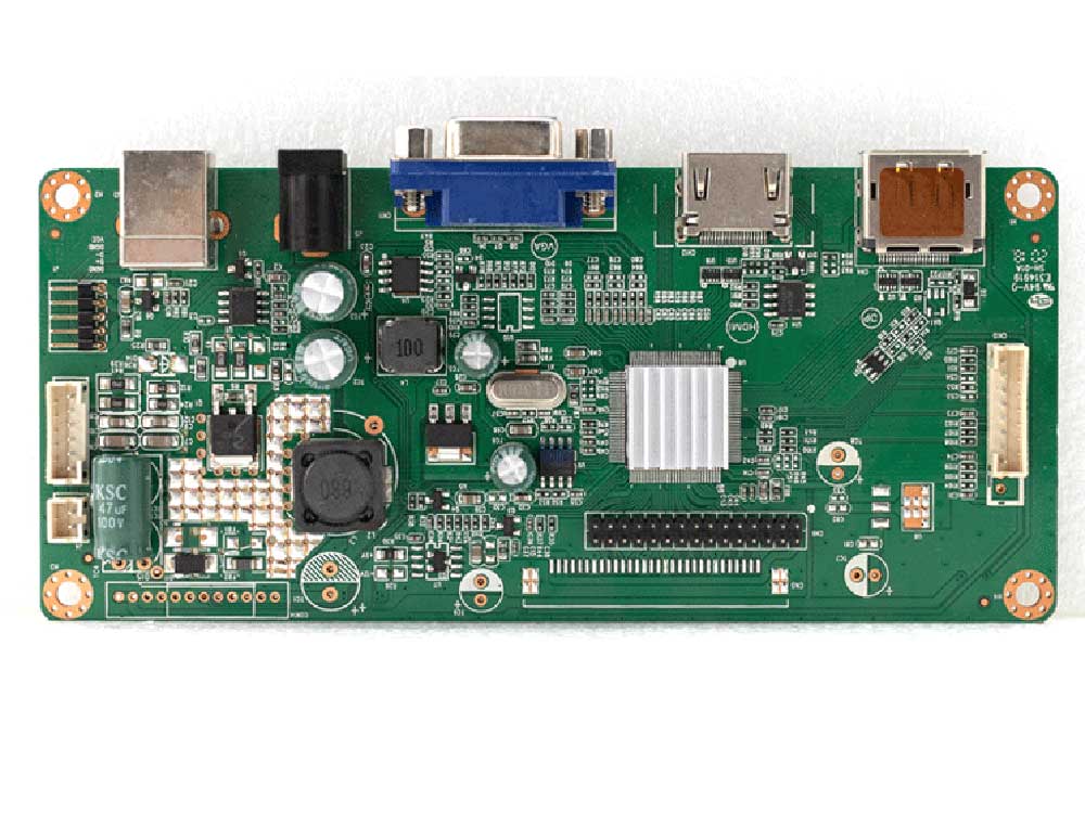
LCD Controller Boards
Review the panel interface, supply, cable and board configuration as a matched display system.
Explore product options →Project review
Plan Your LCD or OLED Module Integration
Send your application, display part number or target specification, controller interface, quantity and assembly arrangement. DisplayMan can review the module, board and cable requirements before quotation or sample evaluation.
Prefer to open the enquiry form here?
Technical References
- EOS/ESD Association: Introduction to ESD
- EOS/ESD Association: Principles of ESD Control
- EOS/ESD Association: Control Procedures and Materials
- EOS/ESD Association: Humidity and ESD Control FAQ
- Newhaven Display: Product Usage Guidelines
- Newhaven Display: Recovery from an ESD Event
- Texas Instruments: System ESD Protection and Layout Resources
General references support the control principles. They do not replace the selected DisplayMan assembly’s approved instructions or establish a certification claim.