OPS Windows PC
Selected models can integrate an OPS PC for Windows applications, enterprise software, Teams, Zoom and browser-based workflows.

Choose a 138″, 145″, 165″, 180″ or 220″ reference model for a straightforward project. For other requirements, build an integrated system from COB, THH, N, T, K or P platform options.
DisplayMan engineers verify the LED modules, driver architecture, control system, power, structure and accessories as one compatible system.
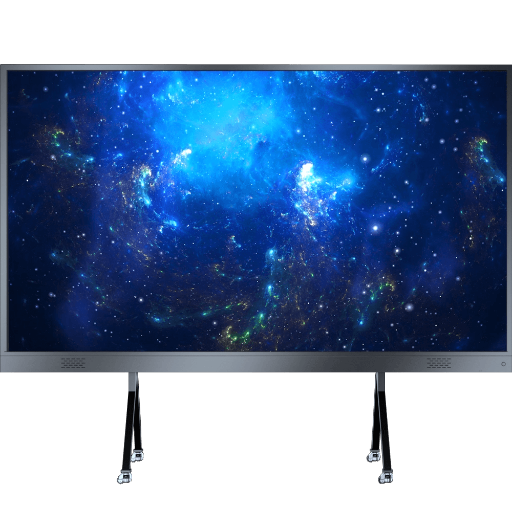
An All-in-One LED Display is a coordinated indoor display system. COB, THH, N, T, K and P are six possible cabinet or module platform families, and each can be used to engineer a complete AIO system.
For a simple purchase, choose an established 138″, 145″, 165″, 180″ or 220″ direction. When the room or target performance calls for something else, dimensions and aspect ratio can be engineered from a compatible cabinet or module grid.
Core components can be selected around your project requirements, with final compatibility verified across the LED module, driver IC, PCB, scan ratio, receiving card, controller, power and structure.
Start with an established 138″–220″ model for a faster, straightforward choice. If the room, screen ratio or performance target needs a different configuration, select from the six platform families and engineer the complete system.
Best for meeting rooms, lecture halls, corporate presentation spaces and other projects where a standard size, integrated controls and simpler deployment are the priority.
Best for luxury home cinema, architectural display walls and premium spaces where the complete system must be engineered around the room and performance target.
| Product Direction | Typical Configuration | Best For | Selection Logic |
|---|---|---|---|
| Standard Integrated AIO LED | 138″ / 145″ / 165″ / 180″ / 220″ reference models | Meeting rooms, lecture halls, enterprise spaces, showrooms | Choose when a standard size and integrated deployment are the priority |
| Configurable AIO LED System | Project-specific width × height, pitch and native resolution | Luxury home cinema, architectural presentation walls, custom enterprise spaces | Choose when the screen must be engineered around the room, resolution and final application |
| AIO LED + OPS / Conferencing | Standard AIO hardware + Windows / camera / microphone options | Hybrid meetings, education, enterprise collaboration | Choose when computing and conferencing must be integrated |
| Mobile AIO LED | Selected standard models + mobile stand | Flexible meeting rooms and multi-purpose spaces | Choose when the finished display may need to move within a facility |
These established models are the simplest starting point for most enquiries. Choose a preset size, then confirm the final configuration and accessories for the installation.
| Model | Size | Reference Resolution | Width Direction | Mounting Direction | Typical Application |
|---|---|---|---|---|---|
| YTJ138T15 | 138″ | 1920 × 1080 | Around 3.0 m | Wall mount / mobile stand | Executive rooms, compact meeting rooms |
| YTJ145V16 | 145″ | 1920 × 1080 | Around 3.2 m | Wall mount / mobile stand | Medium meeting rooms, corporate spaces |
| YTJ165T18 | 165″ | 1920 × 1080 | Around 3.6 m | Wall mount | Boardrooms, training rooms, dedicated media rooms |
| YTJ180V16 | 180″ | 2400 × 1350 | Around 4.0 m | Wall mount | Lecture halls, monitoring and presentation spaces |
| YTJ220T12 | 220″ | 3840 × 2160 | Around 4.8 m | Reinforced wall mount | Large halls, auditoriums, showrooms, premium cinema rooms |
Selected models can integrate an OPS PC for Windows applications, enterprise software, Teams, Zoom and browser-based workflows.
Camera, microphone and audio options can be reviewed for hybrid meetings and education environments.
Front-service module architecture can simplify maintenance in wall-mounted installations with limited rear access.
Brightness, power, OS, inputs, mounting accessories, audio and software configuration can vary by model and final project. Confirm the final project specification before order.
Each series can form a complete AIO display. These are reference cabinet or module specifications from the supplied series datasheets; screen size is configured from the selected platform and installation requirements.
Reference pitches: COB0.78 / COB0.9 / COB1.25 / COB1.56
Reference hardware size: 600 × 337.5 × 30 mm
Ultra-fine COB cabinet platform; pitch and matrix chosen for the target room and resolution.
Reference pitches: T0.9375 / T1.25 / T1.5625 / T1.875
Reference hardware size: 600 × 337.5 × 52 mm
16:9 cabinet geometry for configurable wide-format indoor systems.
Reference pitches: N1.25 / N1.53 / N1.86 / N2.5
Reference hardware size: 640 × 360 × 30 mm
16:9 cabinet platform with several pitch options.
Reference pitches: K1.25 / K1.53 / K1.86 / K2.5
Reference hardware size: 640 × 480 × 49 mm
4:3 cabinet geometry for project-specific screen proportions.
Reference pitches: THH1.25 / THH1.667 (identified models)
Reference hardware size: 400 × 300 × 62 mm
Compact 4:3 cabinet platform; confirm the selected variant and layout.
Reference pitches: P1.25 / P1.53 / P1.86 / P2.0 / P2.5
Reference hardware size: 320 × 160 mm module; cabinet per selection
Modular platform; final cabinet design, dimensions and protection are confirmed per build.
Series specifications describe the reference hardware. The finished AIO display also needs compatible controls, power, mechanics, cabling and factory integration. Available pitches and cabinet options are confirmed during project review.
The system BOM is developed for the room, use case and required performance. Hardware and service options are configurable within a validated engineering architecture.
Components are highly configurable, but they are not mixed arbitrarily. DisplayMan engineers verify compatibility among the LED module, driver IC, PCB, scan ratio, receiving card, controller and power system before finalizing the BOM.
Start with a 138″, 145″, 165″, 180″ or 220″ reference model, or configure a system around the room. Installation and meeting features are selected with the LED platform and verified as part of the complete system.
Wall mounting suits a permanent display location; a mobile floor stand can be reviewed for selected models and rooms that need flexibility.
Confirm wall or floor loading, access for service, power, cable routing and the final support structure before approving the layout.
Depending on the model, discuss wireless content sharing, OPS computing, camera, microphone, speakers and touch as optional features.
Operating system, casting compatibility, interfaces and accessory availability are confirmed against the chosen control system and project requirements.
This U.S. private-cinema project shows what “custom” means beyond changing the diagonal size. The entire screen architecture was defined around the room, native resolution, cabinet matrix, MiniCOB module hardware, high-performance NovaStar control chain, 120 Hz video target, calibration and long-term service strategy.
| Project Parameter | Confirmed Direction |
|---|---|
| Application | Luxury private home theater |
| Screen Class | Approx. 205″ |
| Physical Display Size | Approx. 4800 × 2025 mm |
| LED Technology | P1.25 MiniCOB |
| Cabinet Configuration | 8 × 6 cabinets |
| Cabinet Size | 600 × 337.5 mm |
| Total Cabinets | 48 pcs |
| Native Resolution | 3840 × 1620 |
| Column Driver IC | TBSA1664 |
| Row Driver IC | TBS3008 |
| Scan Ratio | 1/40 |
| LED Refresh Rate | 7680 Hz project configuration |
| Grayscale | 13–16 bit project configuration |
| PCB | 4-layer PCB |
| Video Input Direction | HDMI 2.1 |
| Video Processing | Native 120 Hz point-to-point system design |
| Main Processor | NovaStar MX2000 Pro 5G |
| Input Card | 1 × MX_2×HDMI 2.1 |
| Output Cards | 2 × MX_8×5G Base-T |
| Receiving Cards | 48 × XA50 Pro — one per cabinet |
| Spare Modules | 20 pcs produced with the main batch |
| External Flatness Requirement | ≤0.1 mm overall front-surface target |
| Factory Validation | Complete-screen assembly, calibration and pre-shipment verification |
The project is one example of an AIO system assembled from compatible options; the 205″ diagonal is not a fixed AIO model. The customization is not the diagonal by itself. The real project value comes from matching every system layer — LED module → driver architecture → receiving cards → video processor → signal bandwidth → cabinet mechanics → calibration → verification — to one final application.
DisplayMan starts from the room and application, then works toward the final LED pixel. This is a more useful definition of “All-in-One” than simply mounting a controller behind the screen.
| System Layer | Engineering Review |
|---|---|
| Room / Application | Start from the actual room, viewing distance, content and performance target. |
| Screen Geometry | Define physical width × height, aspect ratio, cabinet matrix and architectural fit. |
| Pixel Pitch & Resolution | Select the pitch from viewing distance and target native resolution. |
| LED Technology | Choose SMD / COB / MiniCOB or other platform according to image quality, protection and budget. |
| Driver Architecture | Match driver IC, scan ratio, grayscale and refresh requirements at module design level. |
| PCB / Module | Confirm PCB structure, module geometry, production lot and LED binning. |
| Power System | Select power-supply architecture and project-grade components appropriate for the load and environment. |
| Receiving Cards | Map receiving-card quantity and load to each cabinet and total screen resolution. |
| Video Processor | Size controller, input cards, output bandwidth and signal chain to the final pixel load. |
| Mechanical Structure | Control module positioning, cabinet alignment, Z-axis flatness and service access. |
| Calibration | Complete optical / system calibration and preserve calibration data for future service. |
| Factory Validation | Assemble the full screen, verify the real signal chain and test the exact production system. |
| Packaging / Numbering | Pack cabinets, modules, cards, cables and spares according to installation sequence. |
| Installation / Commissioning | Use the project drawings, numbering, calibration files and verified settings at site. |
A true high-performance LED system must be engineered from source input to the final LED pixel — not specified by one pixel-pitch or refresh-rate number.
In a high-end MiniCOB project, the LED module is produced for the confirmed system architecture. Driver IC, scan ratio, PCB, grayscale and refresh behavior are not treated as after-sales software choices.
| Hardware Layer | 205″ Case Configuration | Why It Matters |
|---|---|---|
| LED Module | P1.25 MiniCOB produced for the confirmed project architecture | The module is not treated as a generic interchangeable commodity |
| Column Driver | TBSA1664 | Matched to the module and refresh / scan architecture |
| Row Driver | TBS3008 | Part of the production-stage driver design |
| Scan Ratio | 1/40 | Hardware / firmware configuration must match the LED module |
| Refresh | 7680 Hz project configuration | LED refresh is different from source video frame rate |
| Grayscale | 13–16 bit project direction | Reviewed together with driver and brightness settings |
| PCB | 4-layer | Selected as part of the module hardware architecture |
| Spare Modules | 20 pcs, same project production batch | Supports long-term color / brightness matching |
High-precision MiniCOB manufacturing requires specialized SMT, packaging, inspection and process-control equipment. DisplayMan does not need to claim that every component is manufactured in one Shenzhen facility.
The right factory produces the right component, while DisplayMan controls the complete system design, integration and final performance.
High-value projects can specify established power-supply brands such as Megmeet or Mean Well, subject to the final load, voltage and availability. Power is selected as part of the complete BOM rather than treated as an invisible commodity.
The control system is not an accessory added after the LED screen is finished. For the 205″ cinema project, processor capacity, HDMI input, 5G output bandwidth and receiving-card quantity were mapped to the exact 48-cabinet screen.
| Control Layer | 205″ Case Configuration | Engineering Role |
|---|---|---|
| Main Processor | NovaStar MX2000 Pro 5G | Sized around the complete screen and high-bandwidth signal chain |
| Input | MX_2×HDMI 2.1 card | Supports the required HDMI 2.1 source direction |
| Output | 2 × MX_8×5G Base-T cards | Provides the required high-bandwidth cabinet distribution |
| Receiving Cards | 48 × XA50 Pro | One receiving card per cabinet |
| Cabinet Matrix | 8 × 6 | 48 independently mapped cabinets |
| Native Display Resolution | 3840 × 1620 | Derived from the selected screen geometry and LED pitch |
| Video Direction | Native 120 Hz point-to-point | Designed through the full source → processor → receiving card → LED chain |
These are different parts of the system. The LED module can operate at a high refresh rate while the source video path is engineered separately for native 120 Hz. For high-end cinema or motion applications, both layers must be matched through the complete signal chain.
A spare module bought years later may use the same model number but still differ visually from the original screen. High-end systems should plan service inventory at the production stage.
| Planning Item | 205″ Project Direction |
|---|---|
| Main Cabinets | 48 production cabinets assembled for the project |
| Spare LED Modules | 20 spare modules produced together with the main system |
| LED Lot | Same production lot direction |
| Brightness Bin | Same brightness-bin direction |
| Chromaticity Bin | Same chromaticity-bin direction |
| Reason | Reduce visible mismatch when a spare module is needed later |
Spare LED modules can be produced together with the main display using the same production-lot and brightness / chromaticity-bin direction for better long-term visual matching.
At approximately 4.8 meters wide, mechanical flatness becomes an image-quality parameter. Local module steps and cabinet Z-axis errors can remain visible even when the electronics are perfect.
| Mechanical Element | 205″ Project Direction | Purpose |
|---|---|---|
| Module Positioning | Rear positioning pins + backplate positioning holes | Helps control repeatable module placement |
| Module Fixing | Magnetic fixing | Supports front-service removal and controlled seating |
| Module / Backplate Flatness | High-precision surface alignment | Reduces local Z-axis steps across the LED face |
| Cabinet Alignment | Precision flat locking hooks | Keeps adjacent die-cast cabinets on the same front plane |
| X / Y Adjustment | Fine adjustment at cabinet connection points | Supports seam consistency and cabinet alignment |
| Overall Surface Flatness | ≤0.1 mm external project target | Controls the visible continuity of the complete 205″ surface |
Pixel pitch alone cannot create a premium cinema surface. Module seating, backplate accuracy, cabinet machining, locking geometry and installation alignment all influence the final visual continuity.
A high-end LED display should not be treated as complete simply because every pixel lights up. Full-screen calibration and future service data are part of the system.
| Calibration Item | Project Direction |
|---|---|
| Optical Calibration | Complete display brightness / color calibration after screen assembly |
| NovaStar Calibration Data | Calibration configuration retained for future service |
| Backup Files | .ncal and/or .db files depending on calibration workflow |
| USB Backup | Project files and calibration data can be delivered with the system |
| Future Maintenance | Preserved calibration data supports module replacement and system reconfiguration |
| Verification Stage | What Is Reviewed |
|---|---|
| Complete Screen Assembly | All 48 cabinets assembled as the final display geometry |
| Driver / Scan Verification | Confirm production driver IC and scan architecture |
| 120 Hz Signal Verification | Verify the real source-to-pixel processing chain |
| Color / Uniformity Review | Inspect cabinet and module consistency after calibration |
| Temperature / Stability | Operate the assembled system under production-test conditions |
| Software Configuration | Review NovaStar system settings and receiving-card mapping |
| Pre-Shipment Video | Project-specific unedited factory-floor verification can be prepared when agreed |
| Customer Acceptance | Customer reviews the completed system before final shipment stage |
For a high-value custom project, the most meaningful factory test is performed after the exact production screen and control system have been assembled — not on an unrelated stock sample.
A custom screen cannot be fully validated before it exists. The correct workflow is to confirm the engineering, build the real project hardware, integrate the complete system and then perform acceptance testing on the actual production screen.
The exact driver architecture, modules, cabinet matrix, processor configuration and complete screen only exist after project production begins. For customized systems, pre-shipment validation logically happens after the project hardware has been built and integrated.
Separating the LED cabinets, processor, receiving cards and spare inventory into unrelated purchases can make full-system calibration, verification, documentation and packaging more difficult. High-end custom projects are stronger when the complete LED system is engineered and validated together.
All six platforms can support integrated AIO projects. The cabinet, control and accessory configuration follows the room and application.
Custom dimensions, low-pitch MiniCOB, native video processing and silent / premium room integration.
Large seamless presentation screens beyond normal LCD sizes.
Large direct-view screens for presentations, teaching and hybrid communication.
Integrated screens with HDMI, wireless sharing, OPS and conferencing options.
Large-format branded visuals with standard or architectural dimensions.
Integrated large display direction when a standardized system is preferred over a fully custom wall.
| Factor | All-in-One LED Display | Project-Built Indoor Fine Pitch LED |
|---|---|---|
| Product Philosophy | Integrated complete display system | Project-built cabinet video wall |
| Typical Size Direction | 138″–220″ reference sizes or project-defined geometry | Highly flexible custom wall dimensions |
| Control System | Integrated or engineered as part of the complete delivery | Usually selected separately by project |
| Mechanical Design | Finished-display or tightly integrated cabinet architecture | Project support frame + cabinet matrix |
| Factory Integration | Built, configured and tested as one system | Level of full-wall factory integration varies by project |
| Best For | Meeting rooms, cinema, lecture halls, premium presentation spaces | Large custom indoor video walls and architectural installations |
| Factor | All-in-One LED Display | Interactive Flat Panel |
|---|---|---|
| Typical Size | 138″–220″ reference sizes or project-defined large-format direction | 65″ / 75″ / 86″ / 98″ |
| Display Technology | Direct-view LED | LCD |
| Seam / Bezel | Seamless LED canvas | Single-panel LCD |
| Touch | Optional / project-based | Normally standard |
| Close-View Fine Text | Depends on LED pitch | Very strong due to high native pixel density |
| Best For | Large rooms needing a much bigger seamless screen | Standard meeting rooms and classrooms |
| Factor | All-in-One LED Display | Projector |
|---|---|---|
| Image Source | Direct-view self-emissive LED | Projected light |
| Ambient Light | Strong under normal indoor lighting when correctly specified | More sensitive to room lighting |
| Image Geometry | Fixed physical LED canvas | Depends on projector / lens / throw / screen |
| Maintenance | Modular LED components | Optical / projector system maintenance |
| Initial Cost | Higher | Usually lower |
| Best For | Premium permanent large-format display | Cost-sensitive very large image applications |
All-in-One LED is strongest when the room needs a very large seamless direct-view display and the project justifies the higher system investment. Interactive Flat Panels and projectors remain more practical for many smaller or budget-sensitive rooms.
Wall dimensions, viewing distance, content and source video requirements are more useful than asking for a price based only on diagonal size. The best system geometry should be calculated from the actual space.
It means the LED screen is treated as a complete display system rather than only as separate LED cabinets. Depending on the project, this can include LED modules, cabinet mechanics, receiving cards, processor, power, signal architecture, calibration, factory testing, packaging and installation data.
Yes. The 138″, 145″, 165″, 180″ and 220″ reference models provide an easy starting point. Other dimensions and resolutions can be engineered from a compatible COB, THH, N, T, K or P platform.
Yes. The series, pitch, cabinet matrix, video control, power, input architecture, mounting, spares and acceptance plan can be specified for the project. The final BOM is verified for electrical, mechanical and signal compatibility.
Yes, subject to project review. A real U.S. luxury-home-theater project used an approximately 205″ P1.25 MiniCOB display with a custom 4800 × 2025 mm physical size, 3840 × 1620 native resolution and a 48-cabinet system.
No. LED refresh rate and source video frame rate are different parameters. A high-performance system must separately engineer the LED refresh architecture and the end-to-end video-processing chain.
Yes, selected custom systems can be engineered for native 120 Hz point-to-point processing when the source, input card, processor, output bandwidth, receiving cards, driver architecture and LED modules are matched accordingly.
LED batches can differ in brightness and chromaticity. Producing spares with the main display helps preserve better visual matching if a module is replaced later.
For projects using a complete calibration workflow, the relevant NovaStar calibration data and project backup files can be retained and delivered for future service.
For high-value custom systems, full-screen factory assembly and verification can be included so the exact cabinet matrix, control system, calibration and signal chain are tested before shipment.
No claim is made that every specialized component is produced in one factory. DisplayMan controls the system engineering, component selection, supplier coordination, integration, calibration, quality review and final delivery, while specialized MiniCOB production can be assigned to a factory equipped for that process.
Yes. NovaStar is a common professional control direction. The exact processor, input/output cards and receiving cards are selected from total pixels, frame-rate requirements, signal inputs, bandwidth and project architecture.
Yes. Standard All-in-One models can be reviewed with OPS Windows PC, camera, microphone, speakers and wireless-sharing options according to the room workflow.
It is better suited when the required screen is significantly larger than common LCD panel sizes and a seamless LED surface matters. Interactive Flat Panels remain more practical for many standard meeting rooms where touch and lower cost are the priority.
It depends on the project. LED provides a direct-view image and works well under normal indoor lighting, while projectors can be more economical for very large images where the room and optical path are suitable.
Provide wall width × height, room photos, viewing distance, application, source resolution/frame rate, preferred screen size or native resolution, mounting condition, OPS/conferencing/touch requirements, quantity, destination and schedule.
Send the wall dimensions, room type, viewing distance, target resolution, source/video requirements and installation condition. DisplayMan can quote a standard reference model or configure a complete system from six platform families for your room.
We will calculate the compatible cabinet matrix, pixel resolution, control and power configuration before confirming the complete BOM.