Single-eye Micro OLED systems such as EVF, scopes, thermal viewers and compact optical instruments.
Representative platform: 0.49″ FHD + HDMIExplore monocular boardsMonocular, binocular, HDMI, Type-C and custom interface electronics matched to specific Micro OLED display modules for AR, VR, EVF, FPV, HUD and professional optical systems.

DisplayMan supports Micro OLED driver boards for prototype testing, signal conversion and OEM near-eye display integration.
The driver board sits between the host device and the Micro OLED display module. It must match the selected Micro OLED model, resolution, refresh rate, panel interface, power requirement and final system architecture.
This page focuses on Micro OLED driver electronics. The Micro OLED display module and optical engine are separate product categories. Select the display platform first, then match the driver board and optics around the final near-eye system.
Driver-board selection starts from the Micro OLED display and host signal. Different near-eye products need different channel counts, board shapes and interface architectures.

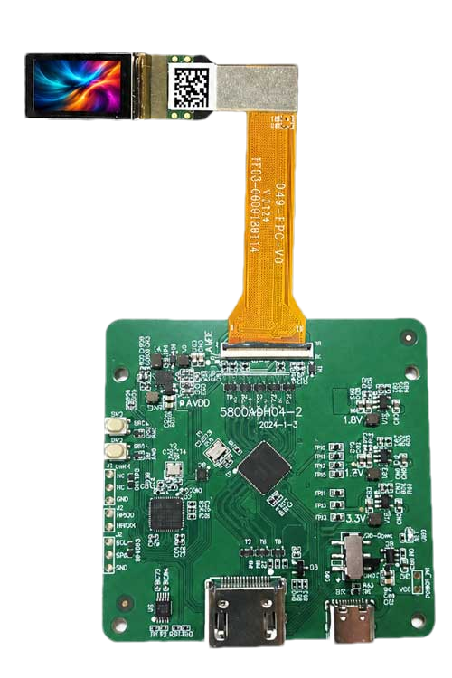
Single-eye Micro OLED systems such as EVF, scopes, thermal viewers and compact optical instruments.
Representative platform: 0.49″ FHD + HDMIExplore monocular boards
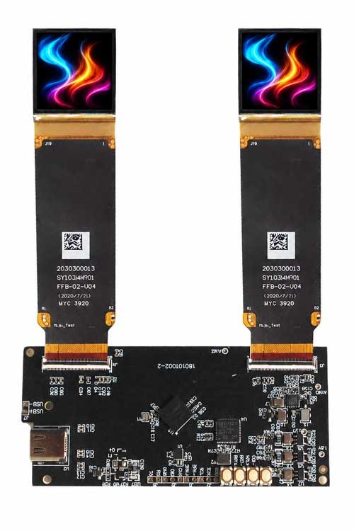
Dual-eye AR, VR, FPV and stereo systems where left and right Micro OLED channels must operate together.
Representative platform: 1.03″ 2.5K + Type-CExplore binocular boards
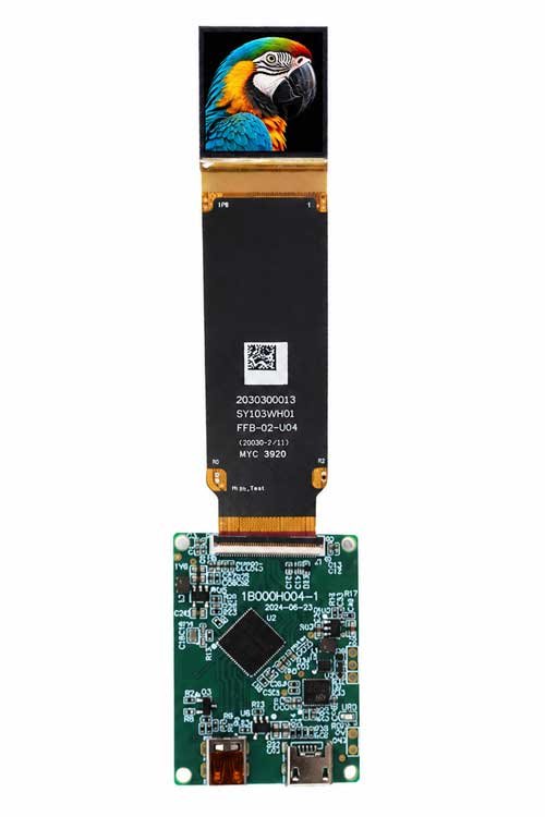
Compact products and prototypes that need a practical external digital-video input matched to the selected Micro OLED.
Representative platform: 1.03″ 2.5K + HDMI MiniExplore HDMI / Type-C boards
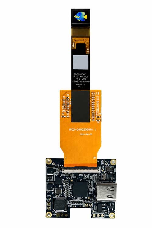
OEM projects that need a non-standard signal path, connector layout, board size, cable architecture or host integration.
Representative platform: 0.32″ SVGA + Compact Type-C MiniExplore custom interface boardsA Micro OLED driver board is not simply an HDMI adapter. It manages the signal path between the host device and the Micro OLED panel while also supporting timing, initialization, power and model-specific control.
Host Signal → Driver Board → Micro OLED Panel Interface → Micro OLED Display
Monocular driver boards are used when only one Micro OLED display channel is required.
Binocular systems use two Micro OLED displays and require left / right channel coordination.
A binocular system should be reviewed as one architecture. Resolution, refresh rate, source format, 2D / 3D behavior, synchronization, cable length, left / right matching and mechanical layout can all affect the design.
Do not assume that two independent single-eye boards automatically create a reliable binocular system. Dual-eye products should be reviewed for signal synchronization and system behavior from the beginning.
| Interface Direction | Where It Is Used | Selection Note |
|---|---|---|
| HDMI / Micro HDMI | Prototype, PC, camera, embedded video source | External video input; requires conversion to the selected Micro OLED panel interface. |
| Type-C | Compact AR / VR / FPV and portable devices | Can combine a compact connector with video / power architecture depending on the board design. |
| CVBS | Selected legacy video, camera and FPV applications | Useful where analog video compatibility is still required. |
| MIPI | Micro OLED panel-side or embedded processor architecture | Common high-speed interface direction for selected Micro OLED modules. |
| RGB | Selected Micro OLED panel platforms and embedded systems | Must be matched to the exact panel timing and connector definition. |
| LVDS / Project Interface | OEM embedded integration | Reviewed when a standard ready-made board does not fit the host architecture. |
A customer may request HDMI or Type-C, while the Micro OLED itself uses MIPI or RGB. The driver board bridges these two interface layers.
A driver board should never be selected only from the connector name. The complete Micro OLED platform and final product architecture must be reviewed.
AR glasses, EVF modules, FPV goggles and other near-eye products often have very limited internal volume. Rigid-flex PCB, FPC length, connector location and cable direction can become as important as the electrical interface.
Board outline, connector height, mounting holes, cable bend direction, heat source location and display / optical-engine position should be reviewed before the final mechanical design is released.
Compact board architecture, low power, Type-C / embedded source review and tight mechanical integration around the optical module.
Binocular synchronization, high-resolution signal handling, refresh-rate requirements and compact dual-eye architecture.
Monocular control, low-latency video, compact board size and reliable signal conversion for camera and imaging systems.
Real-time video input, binocular matching, low latency and portable power requirements.
Project-specific host interfaces, brightness control, mechanical constraints and environmental requirements.
Long operating time, reliability, interface stability, operating temperature and specialized mechanical integration.
| Project Requirement | Recommended Direction | What to Confirm |
|---|---|---|
| One Micro OLED + HDMI input | Monocular HDMI driver board review | Display model, resolution, refresh rate, board size |
| One Micro OLED + Type-C input | Monocular Type-C driver board review | Video source, power architecture, connector direction |
| Dual-eye AR / VR | Binocular driver board | Left / right synchronization, 2D / 3D, resolution, refresh rate |
| FPV dual-eye viewer | Binocular low-latency architecture | Input source, latency, refresh rate, power and mechanical size |
| Very limited internal space | Rigid-flex PCB / compact custom board | Board outline, FPC, bend direction and enclosure |
| Embedded processor with MIPI | Direct / custom MIPI architecture review | Timing, initialization, power and panel compatibility |
| Non-standard connector or host signal | Custom interface board | Signal definition, conversion path, quantity and development scope |
| Not sure which display and board to use | Near-Eye Display Solution review | Application, optics, FOV, mechanics and host electronics |
Micro OLED driver boards are not universal. Development should start from an available Micro OLED display module and its electrical requirements, then customize the surrounding electronics only where the project justifies it.
Continue within the Micro OLED product cluster.
Micro OLED DisplaysParent product family covering Micro OLED modules, driver boards and optical engines. Micro OLED Display ModulesSelect the Micro OLED image-source module before matching the driver electronics. Micro OLED Optical EnginesContinue from electronics to display + optics integration for near-eye systems.Use the system page when the architecture is not yet fixed.
Near-Eye Display SolutionComplete display + electronics + optics + mechanics review for AR, VR, EVF, FPV and optical products.Start from the final device when the correct electronics are not yet known.
Micro OLED for ARCompact electronics for augmented-reality optical systems. Micro OLED for VRHigh-resolution binocular signal and display integration. Micro OLED for EVFCompact monocular electronics for viewfinder systems. Micro OLED for FPVLow-latency video paths for FPV goggles. Micro OLED for HUDNear-eye HUD display and driver integration. Micro OLED for Medical OpticsDriver electronics for medical and professional optical instruments.Send the model number, datasheet or photos of the current module together with your required input signal. That is the fastest way to review driver-board compatibility.
A Micro OLED driver board converts the host video signal and control requirements into the electrical timing and interface needed by a specific Micro OLED display module.
Usually no. A suitable driver board or signal-conversion architecture is required between HDMI and the Micro OLED panel interface.
Yes, Type-C input can be reviewed for selected Micro OLED driver-board configurations. Compatibility depends on the display model, resolution, board architecture and required video format.
A monocular board drives one Micro OLED display channel. A binocular board is designed for dual-eye systems where left and right displays must be driven and synchronized together.
Yes. The appropriate interface direction depends on the selected Micro OLED module and host source. HDMI or Type-C is normally handled on the host side, while MIPI or RGB may be used on the Micro OLED side.
No. Driver boards must be matched to the specific Micro OLED model, resolution, refresh rate, interface, power requirement and connector definition.
Rigid-flex PCB directions can be reviewed for compact optical systems where board space and cable routing are limited.
Project-based connector position, FPC direction and cable routing can be reviewed when the selected platform and mechanical constraints allow it.
2D and 3D display requirements can be reviewed as part of a binocular driver architecture. Final feasibility depends on input signal, synchronization, resolution, refresh rate and firmware.
Brightness-control options can be reviewed according to the Micro OLED model, driver architecture and firmware capabilities.
Possibly. A direct MIPI architecture may still require model-specific timing, power, initialization and control circuitry. The host processor and Micro OLED interface must be reviewed together.
Provide the Micro OLED model if known, resolution, refresh rate, input signal, monocular or binocular requirement, required board size, connector direction, power supply, quantity and prototype or production stage.
Send the Micro OLED model, resolution, input signal, monocular / binocular requirement, board-size limitation and quantity.
A Micro OLED driver board must be matched to the display platform and final system architecture.
Host Signal → Driver Board → Panel Interface → Micro OLED Display
Provide the display model, resolution, input signal, monocular / binocular requirement, board-size limitation, quantity and project stage.
Please share your application, display size, quantity and project background. We will review the most practical display direction.