
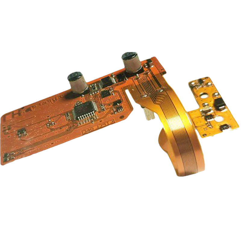
3-Layer 1100 mm Long FPC
| Layers | 3 |
|---|---|
| Length | 1100 mm |
| Thickness | 0.28 mm |
| Minimum Trace / Space | 5 / 5 mil |
| Surface Finish | ENIG |
| Working Temperature | 220°C — oil production application; project conditions to confirm |

DisplayMan helps connect LCD panels, touch sensors, controller boards and backlights with FPC and cable assemblies matched to your product.
Review circuit layout, connector pitch, pinout, routing, stiffeners and shielding around your electrical and mechanical requirements.
DisplayMan supplies custom FPC, FFC and cable assemblies for LCD modules, touch panels, OLED displays, controller boards, LED backlights and OEM display systems.
Standard cables often cannot directly match the connector position, pin definition, cable length, bending direction and mechanical structure of a custom display product.
Project-based support can include LCD panel cables, LVDS, eDP, MIPI, touch FPC, USB touch, backlight cables, adapter cables and complete wire harnesses.
Choose a custom FPC or Cable Assembly when the display, touch panel, controller board, backlight or product mainboard needs matched electrical and mechanical interconnection.
The correct cable depends on display type, interface, connector, pin definition, electrical rating, cable routing and enclosure structure.
| Product Direction | Best For | Selection Logic |
|---|---|---|
| LCD Panel Cable Assembly | TFT LCD panels and display modules | Selected when the panel needs LVDS, eDP, RGB, MIPI or another matched signal cable |
| Touch Panel FPC | Capacitive and resistive touch panels | Selected when the touch sensor needs a custom FPC direction, length, connector or pinout |
| Controller Board Cable Set | LCD controller boards and driver boards | Selected when the board must connect to LCD, touch, keypad, OSD, speaker, IR or power |
| LVDS Cable Assembly | Industrial LCD panels and monitor-style display systems | Selected when the exact panel and controller board use matched LVDS connectors and pin definitions |
| eDP Cable Assembly | Selected high-resolution LCD panels | Selected when eDP signal integrity, connector and cable routing must be matched |
| Backlight Cable Assembly | LED backlights and LCD backlight systems | Selected when voltage, current, polarity, connector, wire length or dimming must be customized |
| Adapter Cable | Replacement, prototype testing and special interface matching | Selected when two connectors or pin definitions do not directly match |
| Wire Harness | OEM equipment and display-system wiring | Selected when multiple signal, power and control wires need an organized assembly |
FPC / Cable Assembly does not display images or control the system by itself. It connects the LCD, touch panel, controller board, backlight and product electronics.
Explore six flexible printed circuit reference projects, including multilayer circuits, long-format FPC, impedance-controlled layouts and component assembly.
| Layers | 3 |
|---|---|
| Length | 1100 mm |
| Thickness | 0.28 mm |
| Minimum Trace / Space | 5 / 5 mil |
| Surface Finish | ENIG |
| Working Temperature | 220°C — oil production application; project conditions to confirm |
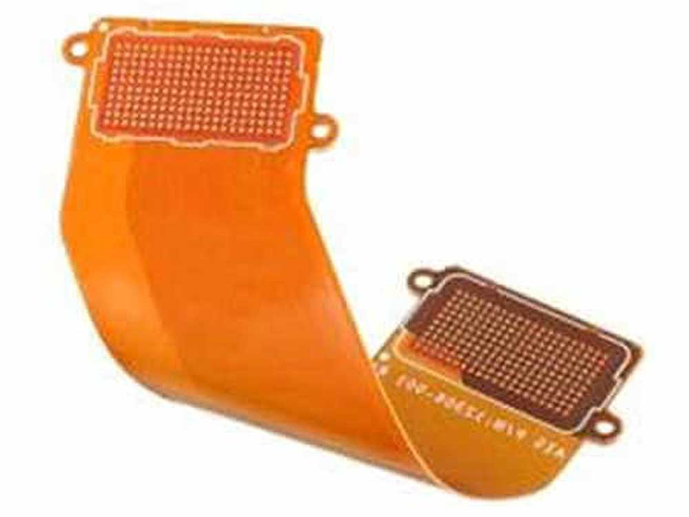
| Layers | 10 |
|---|---|
| Dielectric | Polyimide |
| Thickness | 0.6 mm |
| Minimum Trace / Space | 4 / 4 mil |
| Stiffener | Stainless steel |
| Highlight | Impedance control for high-speed signal transfer |
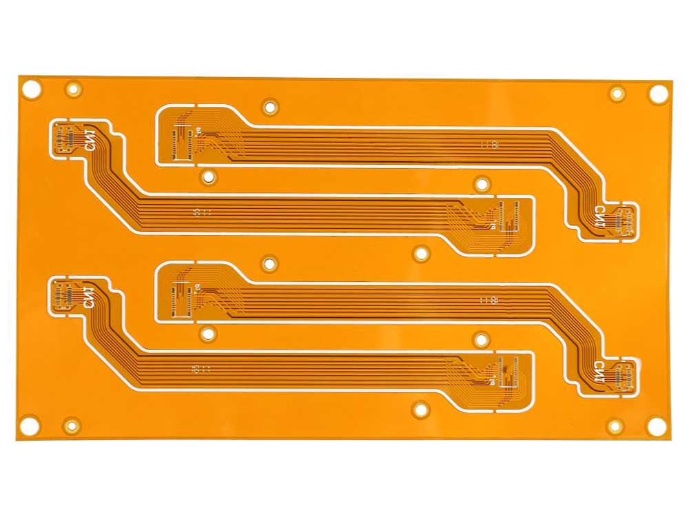
| Layers | 4 |
|---|---|
| Dimensions | 98 × 12 mm |
| Thickness | 0.36 mm |
| Minimum Trace / Space | 4 / 4 mil |
| Surface Finish | ENIG |
| Vehicle Communication | 100 Ω differential pairs and EMI shielding |
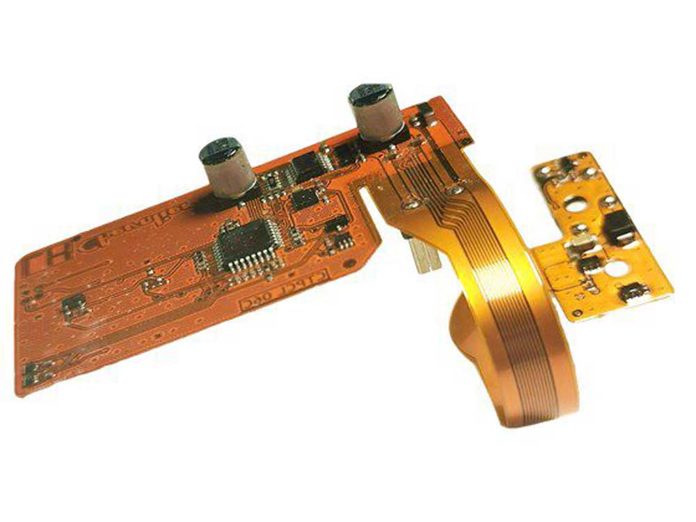
| Layers | 4 |
|---|---|
| Substrate | Polyimide |
| Thickness | 0.36 mm |
| Minimum Trace / Space | 5 / 5 mil |
| Surface Finish | ENIG |
| Assembly | Surface-mounted soldered components |
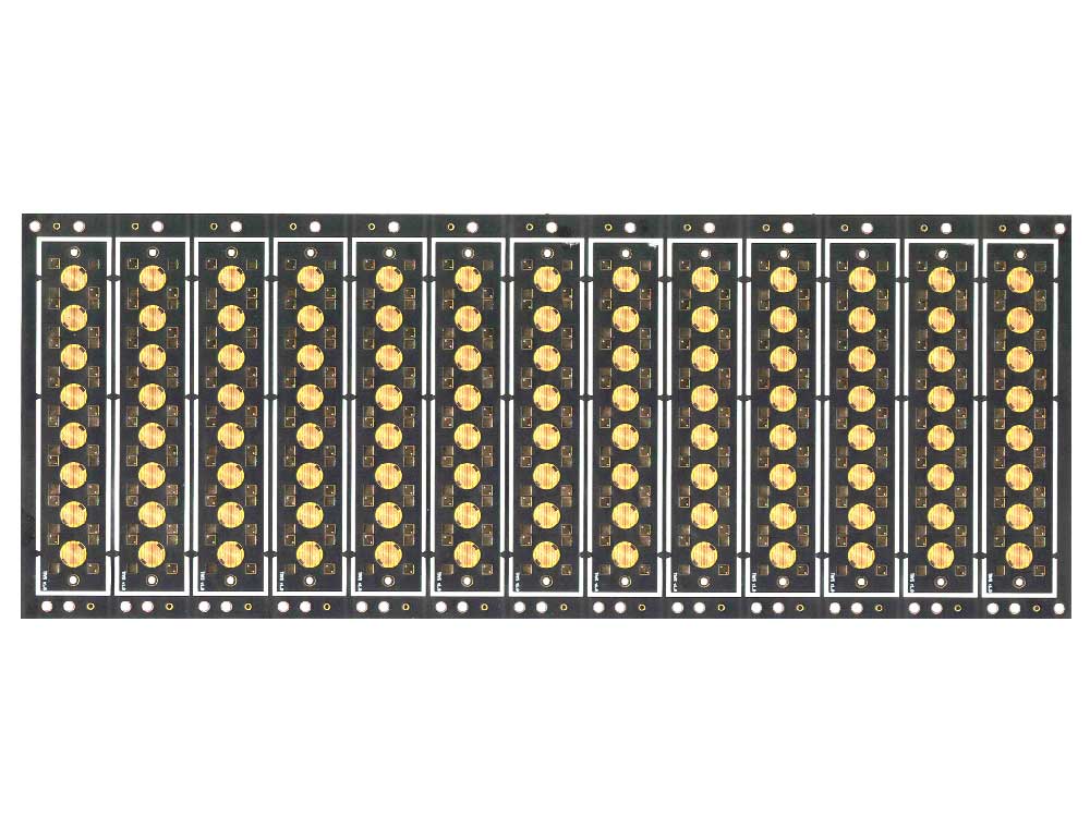
| Layers | 2 |
|---|---|
| Substrate | Polyimide |
| Thickness | 0.1 mm |
| Minimum Trace / Space | 2 / 2 mil |
| Surface Finish | Electroplated gold (3 µin) |
| Stiffener | FR-4 / Polyimide / SUS |
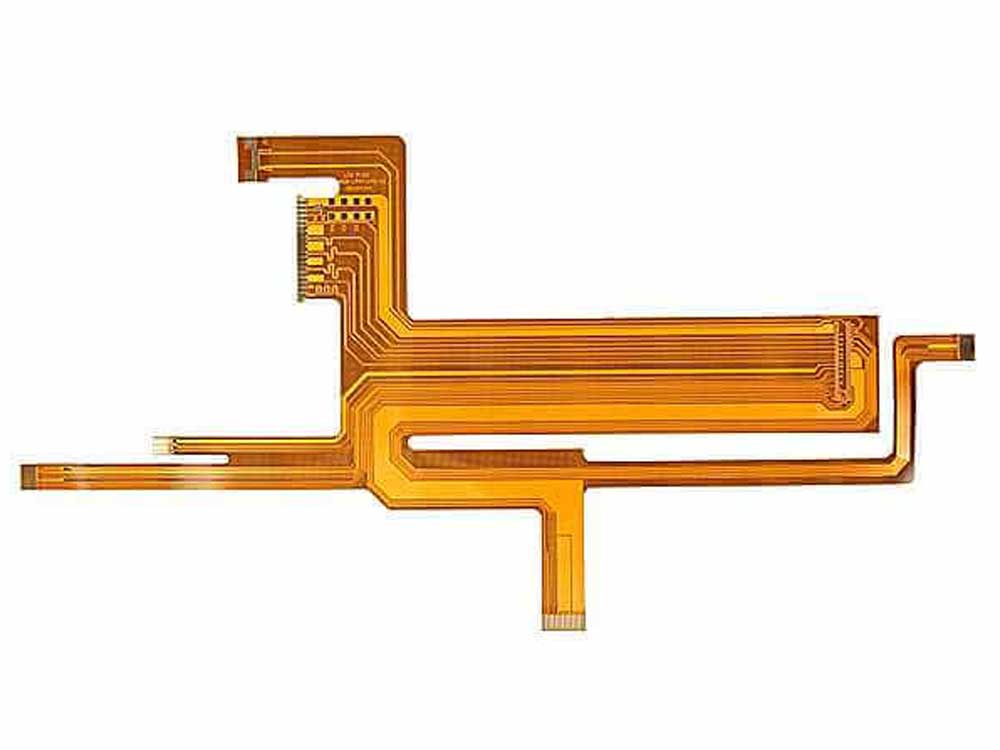
| Layers / Build | 6L, 2-tier |
|---|---|
| Dimensions | 118.29 × 113.12 mm |
| Thickness | 1.3 mm |
| Minimum Trace / Space | 2 / 2 mil |
| Surface Finish | ENIG + OSP |
| Laminate Material | FR-4, polyimide, high Tg, halogen-free, high-speed and high-frequency materials |
These specifications describe individual reference projects. Final materials, tolerances and operating conditions must be confirmed for the selected design.
Connects LCD, touch and controller signals between modules and boards.
Connects backlight, panel power, control and product wiring.
Matches limited space, bending direction, connector position and assembly structure.
LCD panel to controller board, touch panel to controller, backlight to power board, controller board to OSD keypad, or replacement panel to existing product electronics.
| Item | FPC | FFC | Wire Harness |
|---|---|---|---|
| Full Name | Flexible Printed Circuit | Flexible Flat Cable | Cable set with wires and connectors |
| Structure | Printed copper traces on flexible substrate | Flat parallel conductors | Multiple discrete wires assembled with connectors |
| Customization | Shape, traces, stiffener, pads and connector area | Length, pitch, pin count and contact direction | Wire length, color, gauge, connector and grouping |
| Design Flexibility | Highest | More standardized | Flexible three-dimensional routing |
| Best For | Touch panels, compact modules and special routing | LCD panel-to-board flat connections | Power, backlight, control and multi-wire assemblies |
| Selection Logic | Choose for custom circuit layout | Choose when a standard flat cable is enough | Choose for product wiring and power/control lines |
FPC provides the most design freedom. FFC is more standard and cost-effective. Wire Harness is used for grouped power, backlight and control wiring.
| Cable Type | Full Name or Structure | Electrical Structure | Main Review Factors | Typical Use |
|---|---|---|---|---|
| FPC | Flexible Printed Circuit | Printed copper traces on flexible substrate | Shape, traces, pads, stiffener, gold fingers and special routing | Touch panels, compact modules and custom circuit routing |
| FFC | Flexible Flat Cable | Flat parallel conductors | Pitch, pin count, length and same-side or opposite-side contact | Standard panel-to-board flat cable connection |
| LVDS Cable | Low-Voltage Differential Signaling cable | Differential pairs with panel and board connectors | Pinout, channel count, shielding, grounding and routing | Industrial LCD and monitor-style TFT LCD systems |
| eDP Cable | Embedded DisplayPort cable | High-speed differential signal cable | Link routing, impedance, connector, grounding and signal integrity | Modern higher-resolution LCD panels |
| MIPI Cable / FPC | MIPI DSI interconnection | High-speed embedded display routing | Lane routing, impedance, connector and panel-specific design | Compact embedded LCD modules |
| Wire Harness | Grouped wires with connectors | Multiple discrete wires organized into one assembly | Wire gauge, color, length, connector, polarity and grouping | Power, backlight, control and multi-cable assemblies |
LVDS, eDP and MIPI cables must be reviewed for signal integrity, impedance, grounding, shielding, routing and connector matching—not only cable length.
The same connector type does not mean the same pin definition. A wrong cable may damage the LCD panel, controller board, touch panel or backlight.
LCD panel cable selection must be based on the exact panel model and controller-board connector, not only the screen size or resolution.
| Review Factor | What Must Be Confirmed |
|---|---|
| LCD Interface | LVDS, eDP, RGB, MIPI, TTL or another panel interface |
| Panel and Board Connector | Both connector models, pitch, orientation and locking structure |
| Pin Definition | Signal, power, ground, enable, PWM and reserved pins |
| Signal Direction | Correct transmission direction between board and panel |
| Cable Length and Routing | Distance, bend radius, enclosure path and service access |
| Signal Integrity | Impedance, pair matching, grounding and shielding |
| Backlight Connection | Separate or integrated LED power and dimming connection |
| Power Rating | Voltage, current and wire or trace capacity |
Panel datasheet, controller-board connector and pin definition should be reviewed together before production.
Touch-panel FPC should be reviewed with the sensor, controller IC, interface, grounding and enclosure—not only as a mechanical tail.
| Review Factor | What Must Be Confirmed |
|---|---|
| Touch Type | Capacitive or resistive touch |
| Sensor and Controller | Touch sensor structure and controller IC |
| FPC Length and Direction | Routing from sensor to PCB or connector |
| Connector | Type, pitch, pin count and orientation |
| Interface | USB, I2C, SPI or project-based |
| Grounding and Shielding | Anti-interference and ESD performance |
| Bending Area | Avoid stress at IC, bonding and connector areas |
| Enclosure Structure | Space, adhesive, support and assembly path |
For capacitive touch, FPC routing, grounding, shielding and controller position can affect anti-interference performance and assembly reliability.
A controller board should not be reviewed alone. The connection between panel, board, backlight, touch, OSD and power should be checked as one system.
| Item | FPC / Cable Assembly | LCD Controller Board |
|---|---|---|
| Main Function | Connects components | Drives or controls the display |
| Includes IC or Firmware | Usually no | Yes |
| Product Role | Signal or power interconnection | Signal processing and panel driving |
| Selection Logic | Choose when connection matching is required | Choose when signal conversion or display control is required |
| Item | FPC / Cable Assembly | Touch Panel |
|---|---|---|
| Main Function | Electrical connection | Touch sensing |
| Product Scope | Cable, FPC, connector or harness | Sensor, cover glass, FPC and controller |
| Touch Function | No | Yes |
| Selection Logic | Choose for connection matching | Choose for touch input |
| Item | Adapter Cable | Custom FPC |
|---|---|---|
| Main Purpose | Connect existing components with different connectors or pinouts | Create a custom flexible circuit and routing structure |
| Typical Stage | Replacement, prototype or low-complexity conversion | OEM product design and mass-production integration |
| Customization | Connector, pinout, length and wiring | Outline, traces, layers, pads, stiffener and bending area |
| Selection Logic | Choose when cable conversion is enough | Choose when a custom circuit layout is required |
LVDS, eDP, RGB and backlight connections.
Custom FPC, PIN and PCB interconnection.
Compact display FPC and product-mainboard matching.
Sensor FPC, controller IC and USB or I2C connection.
Panel, backlight, power, OSD and touch cable sets.
Voltage, current, polarity and dimming connection.
Custom routing, shielding and durable connectors.
Organized display, touch and power wiring.
Adapter cables, samples and matched pin definitions.
Confirm the exact LCD, touch panel, board, backlight and product mainboard.
Provide connector models, pitch, pin count, orientation and electrical pinout.
Select according to signal type, routing, cost and mechanical structure.
Confirm bending direction, cable path, stiffener and assembly space.
Check voltage, current, impedance, shielding, grounding and temperature.
Test continuity, signal, power, touch, backlight, bend and product fit.
The correct route depends on whether the project needs only interconnection or also display driving, touch sensing, backlight or the LCD module itself.
| Project Requirement | Recommended Product Direction |
|---|---|
| Signal conversion or LCD driving | LCD Controller Boards |
| Custom LCD backlight or illumination system | LED Backlights |
| TFT LCD module itself | TFT LCD Displays |
| TFT LCD module with touch | Touch Screen TFT LCD Displays |
| Custom capacitive touch panel | Capacitive Touch Panels |
| Pressure-based touch panel | Resistive Touch Panels |
| Custom front cover glass | Custom Touch Panel Glass |
| Monochrome LCD module | Monochrome LCD Displays |
| Main component product family | LCD Displays & Components |
Provide clear photos of both cable ends, connector close-ups, pin count, cable length and the connected panel, touch panel or controller board.
FPC means Flexible Printed Circuit. It is a flexible circuit used to connect touch panels, LCD modules, sensors or electronic boards.
FFC means Flexible Flat Cable. It is a flat cable commonly used for LCD panel-to-board connection.
FPC uses custom copper traces and can have a special outline, stiffener and pad design. FFC uses parallel conductors and is normally more standard and cost-effective.
No. It is a connection component used to integrate LCD panels, touch panels, controller boards, backlights and product mainboards.
No. The cable must match the exact panel connector, interface, pin definition, voltage and controller board. A wrong cable can damage the display system.
The exact panel model and datasheet are needed to confirm connector, pinout, interface, signal direction, power and backlight requirements.
Yes. LCD panel cables can be reviewed according to the panel model, interface, connector, pin definition, controller board and mechanical routing.
Yes. LVDS cable assemblies can be reviewed according to the panel, controller board, pinout, cable length, channel count, shielding and grounding.
Yes. eDP cable assemblies can be reviewed according to the panel datasheet, connector, link routing, signal integrity and controller or mainboard compatibility.
MIPI cable and FPC projects require project-based review because lane routing, impedance, connector matching and panel initialization are highly specific.
Yes. Touch-panel FPC can be reviewed for capacitive and resistive touch according to sensor design, FPC direction, connector, controller IC, grounding and enclosure.
Yes. USB touch cables can be reviewed when the touch controller connects to a PC, Android board, industrial computer or other host system.
Yes. Backlight wire, connector, PIN and FPC connections can be reviewed according to voltage, current, polarity, dimming and module structure.
Yes. A cable set may include the LCD panel cable, backlight cable, power cable, OSD keypad cable, USB touch cable, speaker cable, IR cable and adapter cable.
Yes. FPC outline, bending area, copper traces, stiffener, gold fingers, adhesive and connector position can be reviewed.
Yes. Shielding, grounding, conductive tape and EMI-related structures can be reviewed according to the interface, cable length and product environment.
It describes whether the exposed conductors at both cable ends face the same side or opposite sides. This must match both connectors.
Yes. Please provide the old cable sample, photos of both ends, connector close-ups, pin count, cable length and matched panel or board information.
Please provide LED voltage, current, polarity, connector, pin direction, wire gauge, cable length, dimming signal and routing requirement.
Please provide cable type, matched panel, touch panel or board model, connector type, pitch, pin count, pin definition, length, width, contact direction, bending direction, stiffener, shielding, operating temperature, voltage or current where applicable, quantity, drawings and samples.
Send us the cable type, matched panel or board model, connector, pitch, pin count, pin definition, length, contact direction, bending direction, shielding, electrical rating, quantity and drawings.
DisplayMan will review whether the project needs a custom FPC, FFC, LVDS cable, eDP cable, touch FPC, backlight cable, adapter cable or wire harness.
The same connector does not guarantee the same pin definition. The cable must be checked with the actual panel, touch sensor, controller board, backlight and product wiring before production.