High Pixel Density
Micro OLED supports detailed images, text, overlays and measurement information in compact magnified viewing systems.

Match Micro OLED, Driver Electronics and Optics for Your Imaging Instrument
Integrate compact, high-resolution Micro OLED displays with DisplayMan, combining matched driver electronics, near-eye optics and prototype review for medical imaging viewers, microscopes, thermal instruments and professional optical systems.
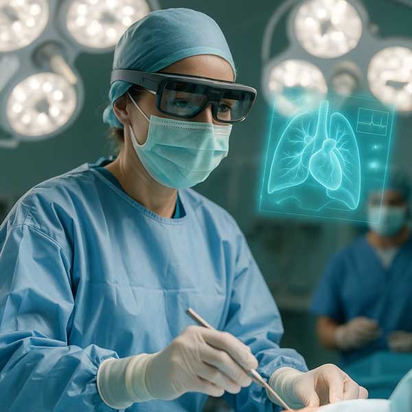
Display + Driver Electronics + Precision Optics
Review image quality, viewing geometry and integration requirements as one system.
Micro OLED is suitable for compact medical imaging viewers and professional optical instruments because it combines high pixel density, true-black contrast, fast response and a small physical image source for magnified near-eye observation.
Final performance depends on display resolution, optical magnification, color and gamma, uniformity, eye relief, focus, driver electronics, latency, cleanliness, mechanical alignment, thermal behavior and the intended regulated use.
DisplayMan supplies display components and selected integration support. Final medical-device certification, clinical validation, risk management and regulatory compliance remain application- and customer-specific.
Micro OLED supports detailed images, text, overlays and measurement information in compact magnified viewing systems.
Self-emissive pixels provide strong contrast and rapid image changes without a separate LCD backlight.
Small physical size supports integration into eyepieces, microscopes, thermal viewers and handheld optical instruments.
The complete instrument—including sensor, processing, optics, calibration, software and validation—determines suitability for the intended medical use.
Compact near-eye viewing for selected diagnostic-support, visualization, inspection and procedural systems where detailed image presentation is required.
Electronic eyepieces, digital microscopes and measurement systems requiring compact high-contrast viewing.
Thermal viewers, fluorescence imaging, inspection optics and other professional instruments using real-time sensor imagery.
A microscope, thermal viewer and medical imaging device can require very different resolution, color, latency, environmental and regulatory performance.
Sensor → Processing / Calibration → Driver → Micro OLED → Optical Module → User
| Display | Resolution | Brightness | Interface | Starting Direction |
|---|---|---|---|---|
| 0.39″ Micro OLED | 1024 × 768 XGA | 600 cd/m² | RGB | Compact microscope, EVF, thermal and optical-viewer direction. |
| 0.49″ Micro OLED | 1920 × 1080 Full HD | 1800 / 3000 / 20000 cd/m² option review | MIPI | Higher-detail 16:9 medical imaging and professional optical R&D. |
| 0.5″ Micro OLED | 1600 × 1200 UXGA | 1000 cd/m² | MIPI | High-resolution 4:3 direction for microscopy, measurement and imaging systems. |
Model selection must be followed by complete-system testing, quality planning and any regulatory validation required by the final device.
Evaluate native pixels together with magnification, optical resolution, usable image area and focus across the field.
White point, grayscale, gamma, color gamut, pixel defects and spatial uniformity may require project-specific criteria and calibration.
Sensor exposure, processing, transport, driver buffering and display scanout all contribute to real-time image delay.
Clinical or measurement suitability requires evaluation of the complete acquisition, processing, display, optical and software chain.
Confirm HDMI, Type-C, RGB, MIPI or other host output, plus panel timing, power, initialization and brightness control.
Match active area, aspect ratio, magnification, eye relief, exit pupil, virtual-image distance, focus and distortion.
Magnified optical systems reveal dust and fibers. Review sealing, cleaning method, display-to-lens alignment, FPC routing and thermal design.
Define acceptance criteria for image quality, appearance, cleanliness, function, environment and change control before production release.
| Project Condition | Starting Direction | Confirm Next |
|---|---|---|
| Compact microscope or thermal viewer | 0.39″ XGA | Optical magnification, RGB timing, eye relief, environment and defect criteria |
| High-detail 16:9 imaging viewer | 0.49″ Full HD | MIPI driver, color, optical resolution, brightness and thermal behavior |
| High-resolution 4:3 microscope / measurement | 0.5″ UXGA | Aspect ratio, optics, processing bandwidth, calibration and mechanics |
| Display and optics undefined | Near-Eye Display Solution review | Application, required detail, optics, signal, space, regulatory scope and budget |
| Existing eyepiece or optical module | Compatible Micro OLED module review | Supported image size, magnification, eye relief, focus, drawing and interface |
Send datasheets, mechanical drawings, optical parameters, current images and your acceptance criteria for an efficient compatibility review.
It offers high pixel density, compact size, strong contrast and fast response for magnified near-eye image viewing.
No. Medical-device certification and clinical validation apply to the final device and intended use, not automatically to the display component.
0.39-inch XGA, 0.49-inch Full HD and 0.5-inch UXGA cover compact through higher-detail directions. Final selection depends on optics and image requirements.
Yes, in electronic eyepiece or digital microscope systems when display size, resolution, optics and interface are compatible.
Evaluate the panel together with driver settings, calibration, optics, sensor, processing pipeline and final viewing conditions.
No. Sensor readout, processing, transport, driver buffering and display scanout all contribute.
Selected projects can be reviewed as Micro OLED, driver electronics and EVF or near-eye optical-module integration.
Define functional, appearance, pixel, uniformity, cleanliness, environmental, traceability and change-control requirements.
Provide application, intended use, image criteria, optics, signal, mechanics, environment, quality scope, quantity and project stage.
Send the application, intended use, image requirements, optical parameters, signal interface and mechanical space.
Engineer and validate the complete imaging path.
Sensor → Processing / Calibration → Driver Electronics → Micro OLED → Precision Optics → User