3552 × 3552 Detail
A square 3.5K image provides extremely high pixel count for demanding immersive and professional systems.

3552 × 3552 Microdisplay for Premium Near-Eye Systems
DisplayMan offers this square-format Micro OLED platform with a micro-lens design for premium VR, simulation, high-FOV binocular HMD and advanced professional imaging systems.
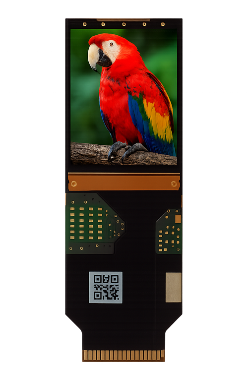
The 1.3″ Micro OLED display is the largest high-resolution square platform in DisplayMan’s broader Micro OLED displays portfolio. SY130LJM01 provides a native 3552 × 3552 resolution across a 23.241 × 23.241 mm active area.
Its 6.543 μm pixel pitch, micro-lens structure and dual-port MIPI architecture make it suitable for premium binocular VR, high-FOV simulation and advanced professional near-eye systems.
The 3552 × 3552 image provides balanced horizontal and vertical resolution with 37.8 million color subpixels.
The panel requires dual-port, 8-lane MIPI DSI electronics. HDMI, Type-C and other sources need a matched high-resolution driver architecture.
The following engineering references are based on the SY130LJM01 pre-specification. Final production specifications, supply status and driver compatibility should be confirmed before design-in.
| Model | SY130LJM01 |
|---|---|
| Display Technology | Active-matrix color OLED-on-Silicon / OLEDoS with micro-lens design |
| Diagonal Size | 1.3 inch |
| Native Resolution | 3552 × 3552 |
| Number of Dots | 37.8 million subpixels: 3552 × 3552 × 3 |
| Pixel Pitch | 6.543 μm |
| Pixel Arrangement | Hexagon, delta arrangement |
| Active Area | 23.241 × 23.241 mm |
| Brightness | 1600 nits at 20% emission duty cycle |
| Contrast Ratio | 200,000:1 |
| Gray Levels | 256 or 1024 |
| Color Depth | 24-bit / 8-bit RGB or 30-bit / 10-bit RGB |
| Frame Rate | Up to 90 Hz |
| Display Interface | Two-port MIPI DSI, 8 lanes total |
| MIPI Data Rate | Up to 1.65 Gbps reference |
| Control Interface | I²C |
| Compression | VESA DSC 1.1; 8/10 bpp and reference 3:1 / 3.75:1 compression |
| Scaling | 1.0× to 2.0× reference support |
| Power Requirements | VDDI 1.8 V, DVDD 1.26 V, ELVDD 3.8 V, ELVSS −7.5 V reference |
| Operating Temperature | −20°C to +70°C |
| Storage Temperature | −40°C to +80°C |
The 1600-nit value is specified at a 20% emission duty cycle. Final brightness, power and thermal performance depend on drive conditions and the complete optical system.
A square 3.5K image provides extremely high pixel count for demanding immersive and professional systems.
The large active area supports high-FOV optics and binocular architectures requiring greater image coverage.
The integrated micro-lens direction supports improved light output, subject to drive and optical-system conditions.
A 90 Hz direction supports smooth near-eye motion when the host, driver and processing pipeline are matched.
Two MIPI ports and eight total lanes provide the bandwidth required for the 3552 × 3552 image.
VESA DSC and scaling support help integrate the high-resolution panel into suitable processing architectures.
High square resolution and a large image area for demanding binocular VR and immersive visualization.
A 3.5K image source for compact folded optics, subject to total transmission and brightness-at-eye evaluation.
High-detail near-eye imagery for aviation, defense, industrial and professional training systems.
A large square image format for dual-display head-mounted systems and wide field-of-view optical designs.
Extremely high pixel count for advanced visualization, inspection and specialized optical instruments.
A high-end platform for evaluating optics, compression, driver bandwidth and custom near-eye architectures.
The display requires a high-bandwidth image pipeline and carefully matched optics. Final perceived resolution depends on the driver, compression, optical MTF, alignment and binocular calibration.
Use the Near-Eye Display Solution page for display selection, driver electronics, optical-engine matching, mechanical integration and prototype evaluation.
The panel, driver, compression, optics, host rendering, mechanics and binocular calibration must be designed together to realize the benefit of 3552 × 3552 resolution.
Compare nine Micro OLED sizes and open the model page that best matches your resolution, optical and mechanical requirements.
SY130LJM01 provides a native 3552 × 3552 square resolution across a 23.241 × 23.241 mm active area.
The pre-specification states 1600 nits at a 20% emission duty cycle. Final brightness depends on drive conditions and the complete optical system.
The panel uses two MIPI DSI ports with eight lanes in total, plus an I²C control interface.
The reference frame rate is up to 90 Hz. The host, driver bandwidth, MIPI configuration and processing pipeline must all support the selected mode.
Normally no. A compatible high-resolution driver architecture must convert the host input into the required dual-port MIPI timing, control and power sequence.
It is a relevant 3.5K direction, but Pancake optics can have significant light loss. Brightness at the eye, field of view, eye box, heat and optical MTF must be evaluated together.
The 1.3″ model provides 3552 × 3552 resolution and a 23.241 mm square active area, while the current 1.03″ direction provides 2560 × 2560 across an 18.432 mm square active area. The 1.3″ platform requires more bandwidth and a larger optical system.
Please provide the application, quantity, required field of view, optical architecture, host input, mechanical envelope, brightness-at-eye target and project schedule.
Send the application, quantity, brightness target, host input, optical requirements, mechanical limits and project schedule. DisplayMan will review whether the 1.3-inch 3.5K direction is suitable.