Type-C Binocular
0.5″ UXGA Micro OLED + Type-C
A compact dual-eye direction for matched 0.5-inch UXGA displays. Confirm the exact panel model, channel timing, connector definition and host video mode.

Coordinated Dual-Channel Control for Binocular Near-Eye Systems
DisplayMan offers dual-channel driver electronics for two matched Micro OLED displays in VR, FPV, stereo viewers and other binocular near-eye systems.
A Binocular Driver Board receives video from a host device and controls two matched Micro OLED displays. It coordinates the left and right channels while managing conversion, timing, initialization, power and display-control functions.
It is used in dual-eye products such as VR headsets, FPV goggles, stereo viewers, simulators and professional binocular optical instruments.
Two displays do not automatically create a reliable binocular system. The displays, driver electronics, source format, refresh rate, left/right timing, cables, firmware and optics must be reviewed together.
The host signal is processed into coordinated left and right channels. The exact route depends on the source format, 2D/3D behavior and selected Micro OLED platform.
Host source → Binocular processing → Left/right panel interfaces → Two Micro OLEDs → Binocular optics
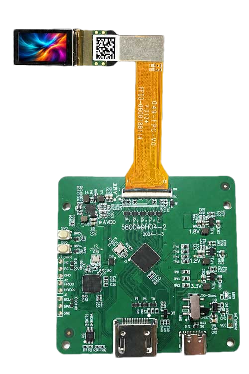
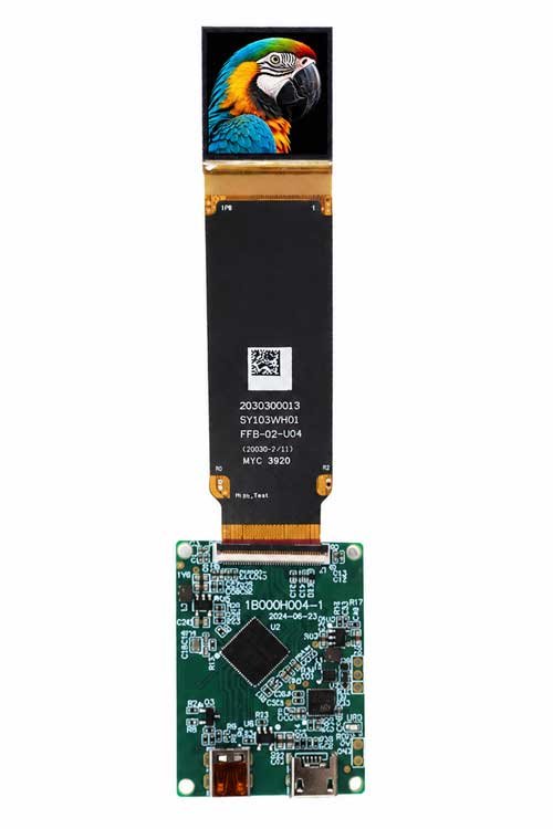
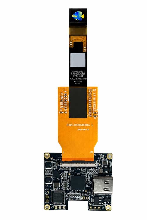
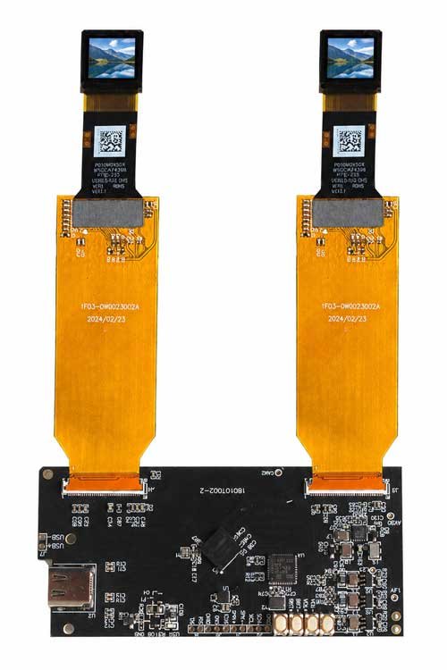
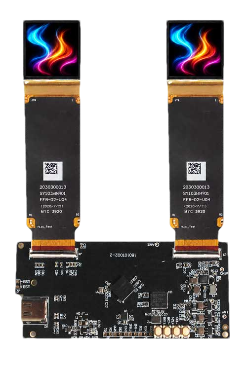
These three real Type-C binocular configurations illustrate matched dual-display directions for 0.5-inch UXGA, 0.72-inch WUXGA and 1.03-inch 2.5K Micro OLED platforms. They are not universal boards: the exact display model, per-eye resolution, timing, firmware, FPC, connector, power architecture and 2D/3D source format must be confirmed for every project.
A compact dual-eye direction for matched 0.5-inch UXGA displays. Confirm the exact panel model, channel timing, connector definition and host video mode.
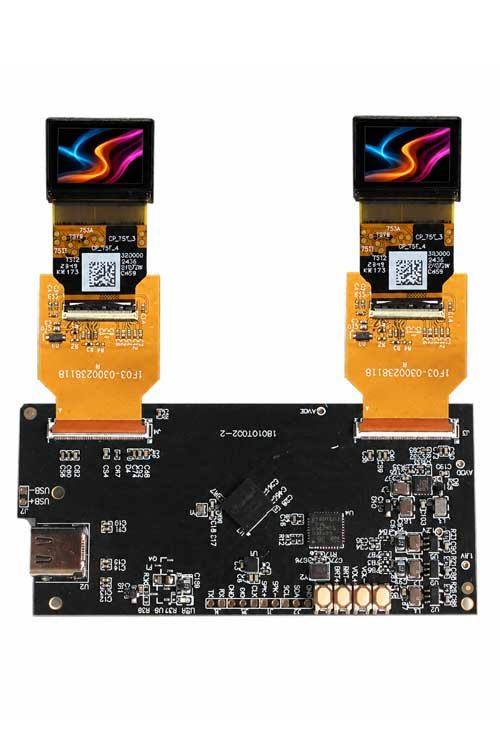
A WUXGA dual-display direction for binocular viewers and development systems. Review bandwidth, refresh rate, left/right routing, FPC and power as one architecture.
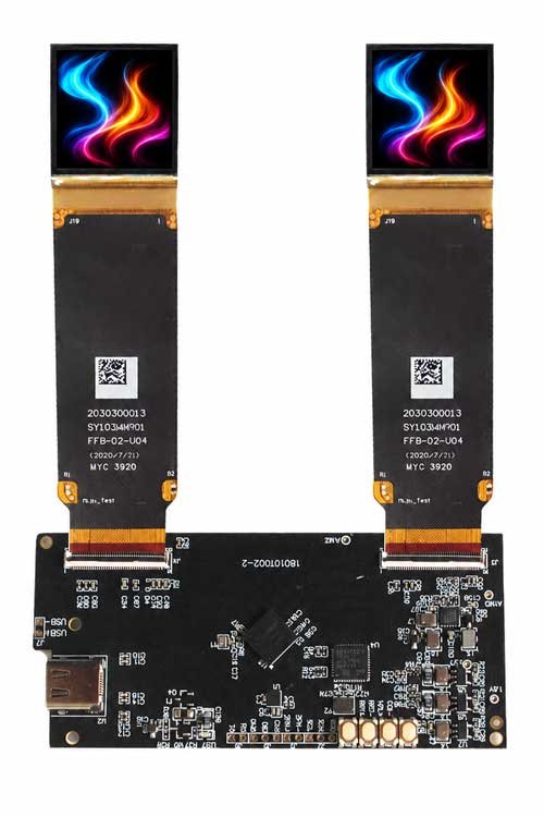
A higher-resolution binocular platform with broad project use and modification potential. Confirm per-eye 2.5K timing, host output, firmware, mechanics and thermal conditions.
| Interface Direction | Typical Position | Binocular Project Note |
|---|---|---|
| HDMI / Micro HDMI | External video input | Useful for PCs, development platforms and prototypes; confirm whether the source carries duplicated 2D content or separate stereoscopic views. |
| Type-C | External video and project-based power path | A compact direction for VR and FPV products; confirm video mode, channel routing, power architecture and host compatibility. |
| CVBS | External analog video input | Not the primary direction for modern high-resolution binocular products; review only for a specific legacy FPV architecture. |
| MIPI | Panel side or embedded host architecture | Lane configuration, bandwidth, timing, initialization and left/right routing must match the exact displays and processor. |
| RGB | Panel side or embedded architecture | Pin definition, bandwidth, timing, voltage and the two connector paths are display-specific. |
| Custom Interface | OEM host or panel connection | Reviewed when the standard board, connector or signal path does not fit the final product. |
A binocular system may accept HDMI or Type-C while both Micro OLEDs use MIPI or RGB. The electronics must bridge the interface layers and coordinate both channels.
The board coordinates initialization, timing, power and image behavior for two matched Micro OLED channels.
A binocular architecture manages frame timing and channel behavior so the two eyes operate as one viewing system.
The board can route duplicated 2D content or project-defined stereoscopic left/right content to the two displays.
HDMI, Type-C or CVBS may be the host input, while MIPI or RGB may be the Micro OLED output. The driver board performs the required conversion between the two sides.
Display size, resolution, interface, connector, pinout, voltage and initialization code must be confirmed first.
Confirm whether the source is HDMI, Type-C, CVBS, USB projection, MIPI, RGB or an embedded processor.
The complete path must support the per-eye resolution, total bandwidth, refresh rate, source format and image orientation.
PCB outline, two display connectors, cable length, left/right routing and control-board placement must fit the headset.
Brightness, image flip, color, gamma and other functions should behave consistently across both display channels.
Two displays increase the power and thermal load; input voltage, current, heat dissipation and standby behavior require system review.
Left/right FPC length, bend direction, connector height and symmetry affect enclosure and optical alignment.
Temperature, continuous operating time, shock, vibration and reliability expectations should be defined for professional products.
Project stage, prototype quantity, expected volume and customization scope help determine whether an existing or custom board is appropriate.
| Driver Direction | Typical Use | Main Strength | Main Review Point |
|---|---|---|---|
| Binocular Driver Board | VR, FPV goggles, stereo viewers and dual-eye systems | Coordinated control for two Micro OLEDs | Synchronization, per-eye resolution, source format, cables and thermal design |
| Binocular Driver Board | VR and dual-eye near-eye systems | Synchronized control of two displays | Left/right timing, resolution, 2D/3D behavior and cable matching |
| HDMI / Type-C Driver Board | Prototype and plug-in video-source systems | Convenient external source connectivity | Input standard, power delivery, conversion path and display support |
| Custom Interface Board | Embedded and product-specific systems | Project-based electrical and mechanical integration | Development scope, firmware, connectors, volume and schedule |
For most OEM projects, begin with an available binocular platform compatible with the selected Micro OLED pair, then review source routing, synchronization, connectors, cables, board outline, power, firmware and controls.
Supported input, resolution, refresh rate, output interface, power, board dimensions and firmware features vary by board and Micro OLED. Final values should be confirmed for the selected configuration.
MICRO OLED DRIVER BOARD FAMILY
It is a dual-channel board architecture that processes a host video signal and coordinates the electrical interfaces, timing, initialization and controls required by two matched Micro OLED displays.
No. Both displays must match the supported resolution, interface, voltage, initialization, connector, pinout, refresh rate and timing requirements.
Usually not. A suitable binocular driver or signal-conversion architecture is required between the host input and the two panel-side interfaces.
Possible directions include HDMI, Micro HDMI, Type-C or an embedded processor on the host side, with two MIPI, RGB or model-specific display paths. Availability is project-dependent.
Brightness, image flip, color, gamma and other functions may be supported. Left/right consistency depends on the board hardware, firmware, displays and project scope.
PCB outline, paired connectors, FPCs, cables and controls can be reviewed. Feasibility depends on the base platform, electrical requirements, tooling, volume and schedule.
Provide both Micro OLED specifications, per-eye resolution, refresh rate, 2D/3D source format, host input, board-size limit, connectors, cables, power, quantity and project stage.
Send the Micro OLED model, per-eye resolution, refresh target, 2D/3D source format, host input, PCB size limit, left/right cables, power, quantity and schedule.