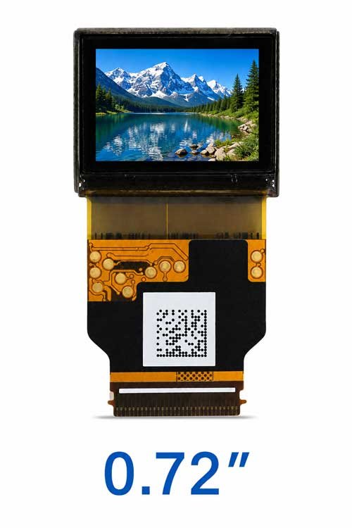
 Display
Micro OLED Selection
Display size, resolution, brightness, interface, refresh rate and optical magnification should be selected around the final application.
Explore Micro OLED Display Modules →
Engineer the Complete Visual Path from Host Signal to the Eye
Develop near-eye visual systems by reviewing Micro OLED selection, driver electronics, optical-engine matching and mechanical integration together. Align resolution, brightness, field of view, eye box, eye relief, input interface and available space with your application before prototype evaluation.
DisplayMan — Your Partner in Near-Eye Display System Engineering
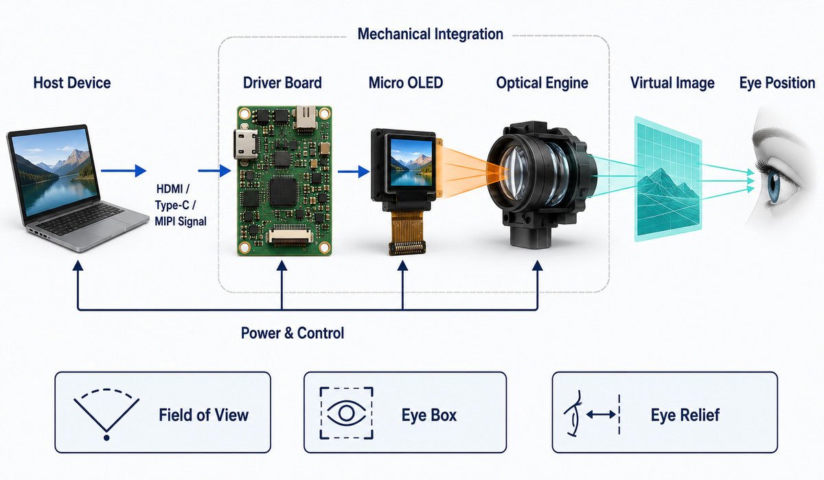
DisplayMan supports near-eye display projects from Micro OLED display selection and driver electronics to optical engine matching, mechanical integration and prototype evaluation.
A near-eye product should not be treated as a microdisplay panel alone. The final image quality depends on the complete path from the host device and driver electronics through the microdisplay and optical engine to the user’s eye.
Display + Electronics + Optics + Mechanics should be reviewed as one system. Resolution, brightness, field of view, eye box, eye relief, optical efficiency, board size, cable routing and mechanical tolerances all influence the final result.
The display image normally passes through lenses, prisms, mirrors, folded optical paths or other optical structures before reaching the eye. The microdisplay is only one part of the system.
Host Device → Driver Board → Micro OLED Display → Optical Engine → User’s Eye
Each layer has a different function, but the layers must be selected and validated as one system. A change in the display, driver timing, optics or mechanical alignment can affect the image finally seen by the user.
| System Layer | Primary Function | Typical Options |
|---|---|---|
| Host / Video Source | Supplies the original image or video data to the near-eye display system. | PC, camera, embedded processor, HDMI, Type-C or CVBS source |
| Driver Electronics | Converts the host signal, controls display timing and provides the power and control required by the selected Micro OLED. | Monocular, binocular, HDMI / Type-C or custom interface board |
| Micro OLED Display | Generates the compact, high-pixel-density source image used by the optical engine. | 0.23″ through 1.30″ OLED-on-Silicon display platforms |
| Optical Engine | Magnifies, redirects and positions the display image to create a viewable virtual image. | Birdbath, Pancake, EVF or project-specific optics |
| Mechanical Integration | Maintains optical alignment, eye relief, focus, thermal control, cable routing and enclosure fit. | Housing, FPC, mounting structure, focus mechanism and thermal management |
| Final Near-Eye Device | Combines the complete visual path around the viewing requirement and final application. | AR glasses, VR headset, EVF, FPV goggles, HUD or medical viewer |
The final near-eye device is not a separate component layer. It is the result of matching the host source, driver electronics, Micro OLED display, optical engine and mechanical structure around one application.
DisplayDisplay size, resolution, brightness, interface, refresh rate and optical magnification should be selected around the final application.
Explore Micro OLED Display Modules →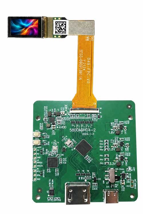 Electronics
Monocular, binocular, HDMI, Type-C, MIPI, RGB and project-specific driver architecture can be reviewed.
Explore Micro OLED Driver Boards →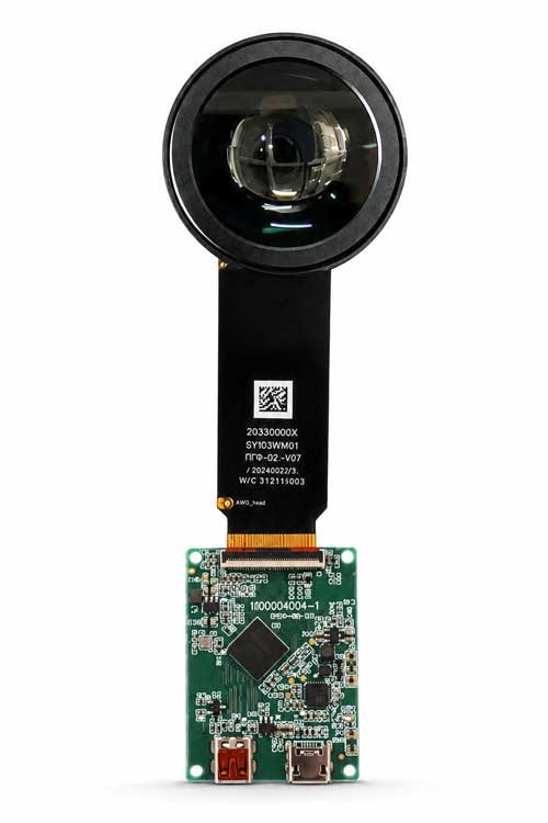 Optics
Birdbath, Pancake, EVF and selected project optical modules can be reviewed according to FOV, eye box, eye relief and mechanical space.
Explore Micro OLED Optical Engines →Micro OLED, also called OLED-on-Silicon or OLEDoS, is especially suitable for near-eye systems because it combines very high pixel density, compact dimensions, self-emissive contrast and fast response.
DisplayMan supports Micro OLED directions from compact SVGA / XGA products through Full HD, UXGA, 2.5K and 3.5K class displays for AR, VR, EVF, FPV, HUD and optical instruments.
Explore Micro OLED Display Modules →
View the Micro OLED Displays parent product page →
A Micro OLED panel normally cannot be connected directly to HDMI, Type-C or another external video source. The panel and driver electronics must be matched together.
| Driver Direction | Typical Use | Interface Direction |
|---|---|---|
| Monocular Driver Board | EVF, scope, thermal viewer, single-eye optical instrument | HDMI / Type-C, CVBS, Micro HDMI or project-based review |
| Binocular Driver Board | AR / VR headset, FPV goggles, stereo viewer | Type-C / Micro HDMI or project-based review |
| Rigid-Flex PCB | Compact optical modules and space-limited products | Project-specific signal architecture |
| Custom Interface Board | OEM near-eye products | MIPI, RGB, HDMI, LVDS, Type-C or project-based review |
Model, resolution, refresh rate, input signal, board dimensions, connector position, cable direction, firmware settings, brightness control and monocular / binocular requirements should be confirmed together.
The Micro OLED image is very small and very close to the eye. An optical engine magnifies and positions the image so it becomes a usable virtual image.
Useful for AR prototypes and selected semi-transparent near-eye systems where a reflective optical structure is acceptable.
Folded optical paths help reduce headset thickness and are common in compact VR and wide-FOV near-eye systems.
Compact electronic viewfinder direction for cameras, drones, professional imaging, inspection and measurement devices.
Start from the final device. The Micro OLED, driver board and optical engine should follow the application instead of being selected independently.
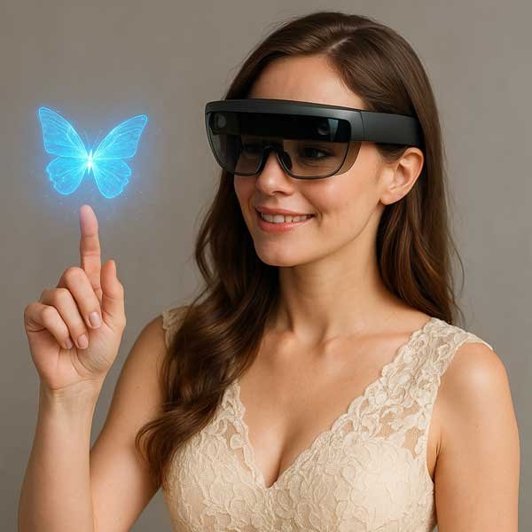
Compact image source integrated with Birdbath, prism, waveguide or another transparent / semi-transparent optical path.
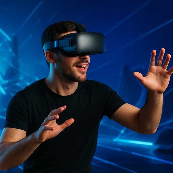
High-resolution binocular systems where pixel density, refresh rate, latency, FOV and compact optical architecture matter.
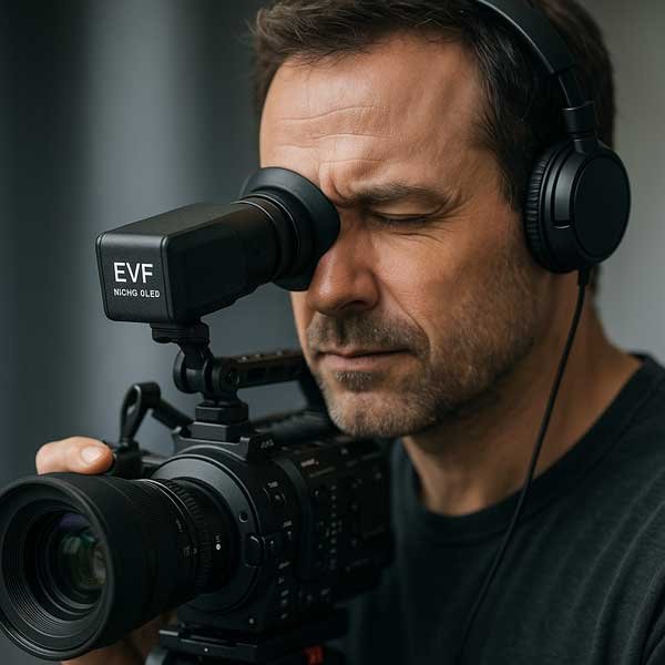
Compact high-quality direct optical viewing for cameras, drones, imaging and professional instruments.

Real-time binocular viewing systems for drones and other low-latency video applications.
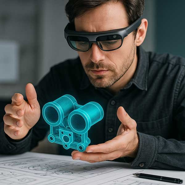
Micro OLED is relevant to compact near-eye and head-mounted HUD systems where the image is viewed through a dedicated optical path close to the eye.
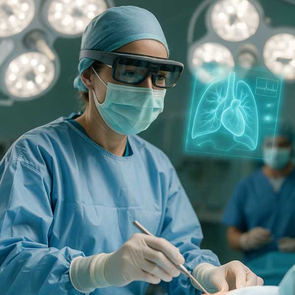
Microscopes, thermal viewers, medical imaging and professional optical instruments often prioritize reliability and optical consistency.
| Customer Requirement | Recommended Direction |
|---|---|
| I already have my own electronics and optics | Micro OLED Display Modules |
| I need HDMI or Type-C video input | HDMI / Type-C Micro OLED Driver Board |
| I need a single-eye viewer | Monocular Driver Board |
| I need dual-eye AR / VR / FPV | Binocular Driver Board |
| I need display + lens as one module | Micro OLED Optical Engines |
| I am developing AR glasses | Micro OLED for AR / Birdbath Optical Engine |
| I am developing VR | Micro OLED for VR / Pancake Optical Engine |
| I need an EVF | Micro OLED for EVF / EVF Optical Module |
| I do not yet know which components to use | Near-Eye Display Project Review |
Start with the final product, required viewing experience and available mechanical space. The display, driver electronics and optical engine can then be selected in the correct order.
A 2.5K or 3.5K microdisplay can still perform poorly if distortion, focus, alignment, brightness or optical efficiency are wrong. A lower-resolution display may be completely suitable for the actual FOV and magnification.
Application → Optical Architecture → FOV → Display Size → Resolution → Brightness → Driver Board → Mechanical Integration
Polarizers, reflective optics, beam splitters, Pancake structures, waveguides, combiners and lens coatings can reduce the light reaching the eye. Panel brightness alone does not predict the final perceived image.
Defines how large the virtual image appears. Wider FOV can increase immersion, but usually increases optical and mechanical complexity.
Defines the area where the user’s eye can move while still seeing the full image. A very small eye box can make the device difficult to use.
Defines the distance between the optical system and the eye. It matters for eyeglass users, protective equipment and head-mounted products.
| Technology | Strength | Typical Near-Eye Direction | Selection Note |
|---|---|---|---|
| Micro OLED | Very high pixel density, true black, high contrast, compact self-emissive structure | AR, VR, EVF, FPV, near-eye / head-mounted HUD and optical instruments | Strong commercial starting point for compact high-resolution near-eye systems |
| LCD Microdisplay | Mature LCD architecture and selected cost-sensitive directions | Specific optical instruments and legacy / cost-driven systems | Requires backlight and normally has weaker black level than Micro OLED |
| LCOS | Reflective microdisplay architecture | Selected projection and near-eye optical systems | Requires external illumination and compatible optical architecture |
| Micro LED | Very high brightness potential and inorganic emitter stability | Ultra-high-brightness AR and selected HUD architectures | Micro LED can follow different optical architectures. For transparent / direct-view see-through HUD, see Transparent Micro LED Displays; this is a different system route from Micro OLED near-eye HUD. |
Micro OLED HUD is primarily a near-eye / head-mounted route using compact optics close to the eye. Transparent Micro LED can be used for transparent / direct-view see-through HUD applications, while conventional non-transparent LCD can also serve as an image source in projection HUD architectures. These approaches should not be treated as the same display system.
Most near-eye projects should select an available Micro OLED semiconductor display platform first, then customize electronics, optics, cables and mechanics around it.
Developing a fully custom Micro OLED semiconductor panel from zero is normally not practical for most OEM projects. The efficient direction is to select the right display first, then customize the supporting electronics, optics and mechanics.
Choose when the hardware direction is already clear.
Micro OLED DisplaysParent Micro OLED product family for near-eye and optical systems. Micro OLED Display ModulesCompare Micro OLED sizes, resolution classes, brightness directions and interfaces. Micro OLED Driver BoardsMonocular, binocular, HDMI / Type-C and custom-interface electronics. Micro OLED Optical EnginesBirdbath, Pancake, EVF and other near-eye optical modules. Transparent Micro LED DisplaysAdjacent transparent-display route for see-through / direct-view HUD concepts; not the same architecture as Micro OLED near-eye systems.There is one system-level solution page for the complete near-eye display architecture.
Near-Eye Display SolutionDisplay + electronics + optics + mechanics system engineering on this page. System Selection ReviewChoose panel-only, driver-board, optical-engine or complete-system direction. OEM / ODM Engineering & PrototypingEngineering support for electronics, optics, mechanics, prototype evaluation and production preparation. Project Review / RFQSend FOV, eye relief, eye box, signal, mechanics, quantity and project stage.Go directly to the application page when the final device is already known.
Micro OLED for ARAR glasses, Birdbath, prism, waveguide and compact smart-eyewear integration. Micro OLED for VRHigh-resolution binocular systems and compact Pancake optical architectures. Micro OLED for EVFElectronic viewfinders for cameras, drones and professional imaging equipment. Micro OLED for FPVLow-latency binocular Micro OLED systems for FPV goggles. Micro OLED for Near-Eye HUDCompact Micro OLED image-source review for near-eye and head-mounted HUD systems. Micro OLED for Medical OpticsMedical, microscope, thermal imaging and professional optical instruments.If available, send lens information, field of view, eye relief, eye box, optical layout, housing drawing or photos of the current prototype. These inputs can change the correct Micro OLED and optical-engine direction.
A near-eye display is a compact display system designed to present an image very close to the user’s eye through lenses, mirrors, prisms or another optical structure.
Yes. Micro OLED is widely used for near-eye applications because it provides high pixel density, compact size, high contrast, true black and fast response.
Usually yes if the display is viewed close to the eye. The Micro OLED image normally needs magnification or projection optics before it can be viewed comfortably.
Usually not. A suitable driver board is normally required between the HDMI or Type-C source and the Micro OLED display.
The Micro OLED is the image source. An optical engine combines the display with lenses, prisms, mirrors or other optical components to create the virtual image seen by the user.
Selected projects can be reviewed as display + driver board + optical engine + mechanical integration rather than panel-only supply.
Birdbath uses a reflective optical path and is common in selected AR systems. Pancake uses a folded optical path and is often selected for compact VR and wide-FOV systems. Final selection depends on brightness, field of view, optical efficiency and mechanical size.
Resolution should be selected together with display size, field of view, optical magnification, viewing requirement and final product application. Higher resolution is not automatically necessary for every near-eye device.
Optical systems can lose significant light through lenses, combiners, polarizers or reflective structures. AR and near-eye / head-mounted HUD systems may therefore need higher source brightness than enclosed EVF or some VR systems.
Yes. Both single-eye and dual-eye driver and optical configurations can be reviewed according to the final product.
Most projects use existing Micro OLED semiconductor display platforms. Customization is usually focused on driver electronics, cable, optical engine, mechanics, firmware and system integration.
Send the application, required resolution, brightness, field of view, eye relief, eye box, display size, input signal, optical-engine requirement, mechanical space, quantity and project stage.
Send the application, required field of view, resolution, brightness, input interface, optical structure, available mechanical space and quantity.
A successful near-eye display starts with the complete optical system, not only the microdisplay.
Micro OLED Display → Driver Board → Optical Engine → Mechanical Integration