OLED Displays & OEM Integration

PMOLED Displays

Compact OLED Modules for Instruments and OEM Products

Explore compact PMOLED modules for text, icons and graphic interfaces in instruments, meters and controllers.

Review resolution, driver IC, interface, connector and mechanical integration around your product requirements.

Text & GraphicsCompact ModulesOEM Integration
1.54-inch white PMOLED display module with 30-pin FPC, KD0154WEOLN006

PMOLED Modules for Text, Icons and Compact Graphic Interfaces

Choose a PMOLED module for a compact interface that shows readings, status messages, icons or simple menus. The six examples below cover white and green monochrome modules from 0.91 to 5.5 inches, including a thin FPC module and wider status-display formats.

Start with the product images and specifications, then compare the module outline, active area, interface and driver IC with your design. For an existing product, send the original display datasheet and connector details so we can review a replacement.

PMOLED Display Products

Explore six monochrome PMOLED modules from 0.91 to 5.5 inches. Click a product image to view it at full size; compare the model, interface, connector and mechanical dimensions below.

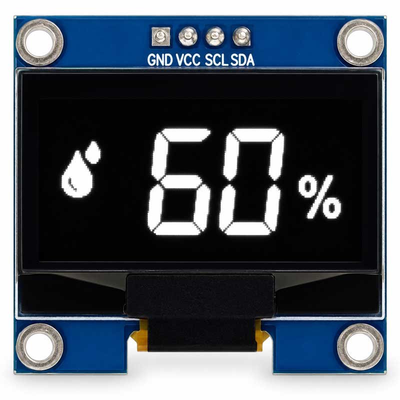
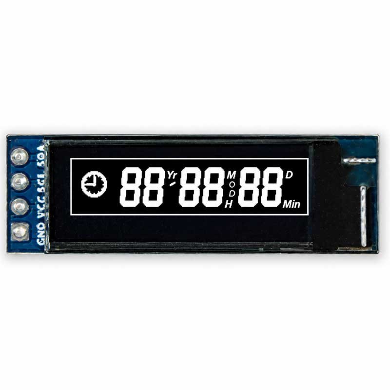
0.91-inch 128 × 32 White PMOLED Display, KD0091SQOIN001

0.91-inch 128 × 32 White PMOLED Display

KD0091SQOIN001

Part No.KD0091SQOIN001
Resolution128 × 32
Display ColorWhite
InterfaceI²C
Driver ICSSD1306
Pins / Pitch4 pins, 2.54 mm
ConnectionSoldering
Module Dimensions38.00 × 12.00 × 3.80 mm
Active Area22.38 × 5.58 mm
Luminance180 cd/m²
Contrast2,000:1
Input Voltage3.3 V
Lifetime50,000 h
Operating Temperature−40 to +70 °C
Storage Temperature−40 to +85 °C
1.3-inch 128 × 64 White PMOLED Display, KD013SQOIN012

1.3-inch 128 × 64 White PMOLED Display

KD013SQOIN012

Part No.KD013SQOIN012
Resolution128 × 64
Display ColorWhite
InterfaceI²C
Driver ICSH1106
Pins / Pitch4 pins, 2.54 mm
ConnectionSoldering
Module Dimensions35.40 × 33.50 × 4.00 mm
Active Area29.42 × 14.70 mm
Luminance150 cd/m²
Contrast2,000:1
Input Voltage3.3 V
Lifetime50,000 h
Operating Temperature−40 to +70 °C
Storage Temperature−40 to +85 °C
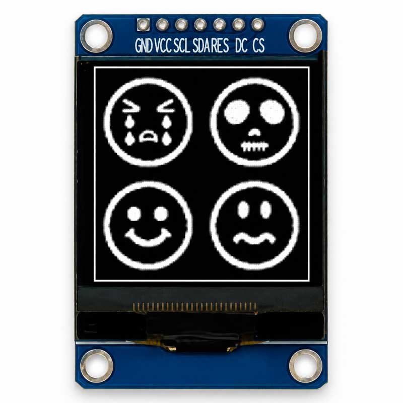
1.5-inch 128 × 128 White PMOLED Display, KD015SQOSN013

1.5-inch 128 × 128 White PMOLED Display

KD015SQOSN013

Part No.KD015SQOSN013
Resolution128 × 128
Display ColorWhite
InterfaceSPI / I²C
Driver ICSH1107
Pins / Pitch7 pins, 2.54 mm
ConnectionConfirm for project
Module Dimensions34.00 × 49.30 × 5.00 mm
Active Area26.86 × 26.86 mm
Viewing Area28.86 × 28.86 mm
Luminance100 cd/m²
Contrast>10,000:1
Input Voltage3.3 V
Lifetime10,000 h
Operating Temperature−40 to +70 °C
Storage Temperature−40 to +85 °C
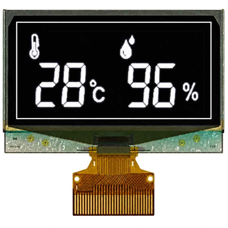
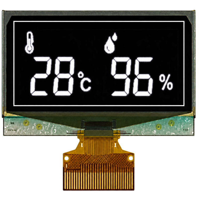
1.54-inch 128 × 64 White PMOLED Display, KD0154WEOLN006

1.54-inch 128 × 64 White PMOLED Display

KD0154WEOLN006

Part No.KD0154WEOLN006
Resolution128 × 64
Display ColorWhite
Response Time10 μs
InterfaceParallel / SPI / I²C
Driver ICSSD1309ZC
Pins / Pitch30 pins, 0.5 mm
ConnectionPlug-in FPC
Module Dimensions42.04 × 27.22 × 1.46 mm
Active Area35.04 × 17.51 mm
Viewing Area37.04 × 19.51 mm
Luminance120 cd/m²
Contrast10,000:1
Input Voltage2.8 V
Lifetime10,000 h
Operating Temperature−40 to +70 °C
Storage Temperature−40 to +85 °C
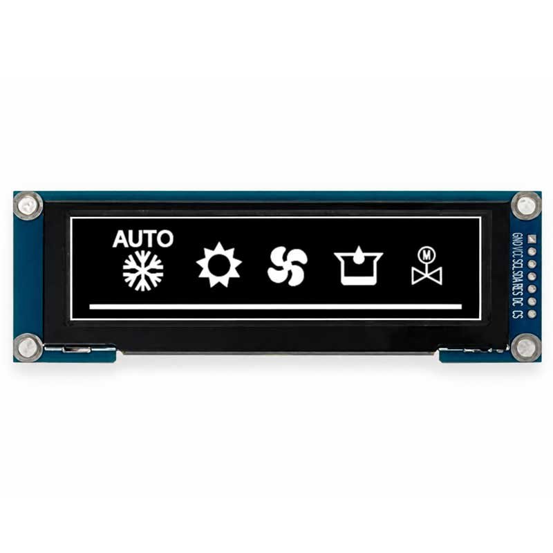
3.1-inch 256 × 64 White PMOLED Display, KD031SCOSN004

3.1-inch 256 × 64 White PMOLED Display

KD031SCOSN004

Part No.KD031SCOSN004
Resolution256 × 64
Display ColorWhite
InterfaceSPI
Driver ICSSD1322
Pins / Pitch7 pins, 2.54 mm
ConnectionPlug-in
Module Dimensions102.00 × 35.00 × 6.60 mm
Active Area76.78 × 19.18 mm
Luminance80 cd/m²
Contrast>2,000:1
Input Voltage3.3 V
Lifetime10,000 h
Operating Temperature−40 to +70 °C
Storage Temperature−40 to +85 °C
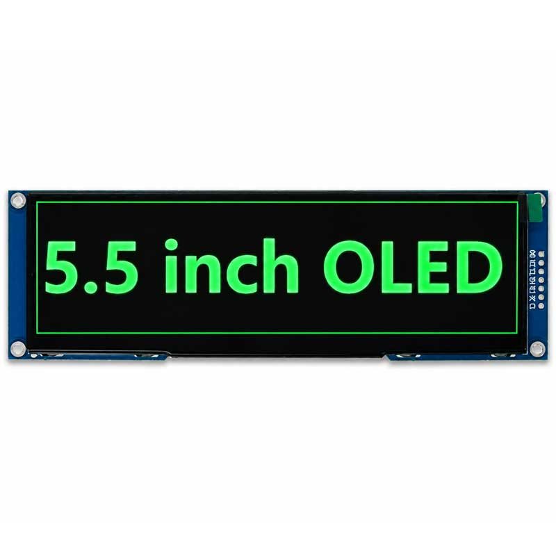
5.5-inch 256 × 64 Green PMOLED Display, KD055SCOSN025

5.5-inch 256 × 64 Green PMOLED Display

KD055SCOSN025

Part No.KD055SCOSN025
Resolution256 × 64
Display ColorGreen
InterfaceSPI
Driver ICSSD1322
Pins / Pitch6 pins, 2.54 mm
ConnectionPlug-in
Module Dimensions160.00 × 50.00 × 6.60 mm
Active Area135.65 × 33.89 mm
Luminance80 cd/m²
Contrast2,000:1
Input Voltage3.3 V
Lifetime40,000 h
Operating Temperature−40 to +70 °C
Storage Temperature−40 to +85 °C

PMOLED Display Reference Lineup

These six models are reference examples. Confirm availability and final specifications for your project, particularly pinout, interface mode, supply conditions and mounting design.

DisplayResolutionInterfaceDriver ICPart No.Example Use
0.91″ White PMOLED128 × 32I²CSSD1306KD0091SQOIN001Long, narrow instrument readouts
1.3″ White PMOLED128 × 64I²CSH1106KD013SQOIN012Meters, controllers and compact instruments
1.5″ White PMOLED128 × 128SPI / I²CSH1107KD015SQOSN013Square icon and graphic interfaces
1.54″ White PMOLED128 × 64Parallel / SPI / I²CSSD1309ZCKD0154WEOLN006Thin FPC module integration
3.1″ White PMOLED256 × 64SPISSD1322KD031SCOSN004Wide industrial status panels
5.5″ Green PMOLED256 × 64SPISSD1322KD055SCOSN025Large monochrome equipment readouts
Important Selection Rule

Match size, resolution, color, interface, driver IC, module outline, FPC or PCB connection, environment and supply availability before selecting a replacement.

What Is a PMOLED Display?

Passive-Matrix OLED

PMOLED means Passive-Matrix Organic Light-Emitting Diode. Rows and columns are scanned to control pixels.

Small and Simple UI

PMOLED is best suited to small display areas, monochrome content, icons, characters and status information.

Self-Emissive Structure

No separate LCD backlight is required because the OLED pixels emit light directly.

PMOLED Is Commonly Used To Show

  • Numbers
  • Characters
  • Icons
  • Status indicators
  • Simple menus
  • Warning messages
  • Measurement values
  • Device settings
Core Boundary

PMOLED is not the right direction for large full-color video, complex animation or high-resolution graphical UI.

What PMOLED Adds to a Compact Product

Self-Emissive Display

OLED pixels produce their own light, so the display does not need a separate backlight. This suits compact front panels showing text and status information.

Simple Graphic Interfaces

Use the pixel matrix for readings, symbols and menus. Select the resolution and active area around the information your users need to read.

Module-Level Selection

The examples include I²C, SPI and parallel interface options. Confirm the selected module’s wiring and interface configuration before designing the mainboard.

Integration Review

Compare the display outline, mounting space, connector and driver IC early. Matching screen size alone does not establish replacement compatibility.

PMOLED Technology Comparisons

PMOLED Displays vs AMOLED Displays

FactorPMOLED DisplaysAMOLED Displays
Driving MethodPassive-matrix row and column scanningActive-matrix pixel control
Display SizeUsually small sizesSmall to medium sizes
ResolutionLower resolution and simple UIHigher resolution and richer UI
Color DirectionUsually monochrome or simple colorUsually full-color
Content TypeText, icons, simple graphics and status dataImages, animations, dynamic UI and full-color interface
InterfaceCommonly I2C, SPI or parallelCommonly MIPI, SPI or project-based
Cost DirectionMore practical for small simple displaysHigher cost with stronger visual performance
Best ForInstruments, meters, controllers and compact devicesWearables, smart devices, handheld products and premium UI
Selection LogicChoose for small simple OLED displayChoose for full-color OLED performance

PMOLED Displays vs Monochrome LCD Displays

FactorPMOLED DisplaysMonochrome LCD Displays
Light SourceSelf-emissive OLED pixelsReflective, transmissive or backlit LCD
BacklightNot requiredMay be required depending on LCD type
ContrastHigh contrast in controlled environmentsDepends on LCD mode and lighting
Power BehaviorDepends on lit pixels and contentReflective LCD can be extremely low power
Outdoor SunlightNeeds careful reviewReflective LCD can perform very well
Static ContentOLED lifetime and image retention should be reviewedUsually more practical for long static content
Custom Segment DisplayLess commonVery common and cost-effective
Best ForCompact OLED UI, icons and small graphicsSegment displays, character displays and low-power instruments
Selection LogicChoose for self-emissive OLED appearanceChoose for ultra-low power, sunlight readability or custom segment LCD

PMOLED Displays vs TFT LCD Displays

FactorPMOLED DisplaysTFT LCD Displays
Display ContentSimple text, icons and monochrome graphicsFull-color UI, images, video and complex menus
Size DirectionSmall sizesSmall to large sizes
BacklightNo backlight requiredBacklight required
InterfaceI2C, SPI or simple controlRGB, LVDS, MIPI, SPI and controller-board options
Cost DirectionPractical for small OLED UIPractical for full-color display modules
Static UINeeds OLED lifetime reviewUsually better for long static UI
Best ForMeters, controllers and compact devicesHMI, terminals, instruments and smart products
Selection LogicChoose for small simple OLED displayChoose for full-color graphical display
Core Comparison

Choose PMOLED for a small self-emissive OLED status display. Choose AMOLED for full-color OLED performance, Monochrome LCD for very low power or long static content, and TFT LCD for larger full-color graphical UI.

PMOLED Engineering Review Factors

A correct PMOLED solution depends on the module, driver IC, firmware, connector, operating content, mechanical fit and supply plan.

Size and Resolution

PMOLED modules are normally selected from existing standard sizes. Common resolutions include 128 × 64 and 256 × 64.

  • UI content
  • Active area
  • Mechanical space
  • Viewing area
  • Standard module availability

Display Color

Many PMOLED modules are monochrome, including white, blue, yellow and green. PMOLED is not normally selected for rich full-color UI.

  • Monochrome color
  • Background appearance
  • Contrast expectation
  • Optical filter
  • Content type

Interface

I2C and SPI are common PMOLED interfaces. The selected interface must match the MCU, mainboard, firmware and connector design.

  • I2C
  • SPI
  • Parallel / project-based
  • MCU compatibility
  • Firmware requirements

Driver IC

The driver IC affects command set, firmware, interface compatibility and replacement possibility.

  • IC model
  • Command set
  • Pin definition
  • Initialization
  • Replacement compatibility

FPC and Connector

FPC length, connector pitch, pin definition and installation direction must fit the PCB and enclosure.

  • FPC length
  • Connector pitch
  • Pin definition
  • Installation direction
  • PCB space

Operating Content

Static or semi-static icons and text require OLED lifetime and image-retention review.

  • Static icons
  • Daily operating hours
  • Brightness
  • Duty cycle
  • Content movement

Mechanical Structure

Module outline, active area, connector direction and mounting structure must fit the final product.

  • Outline size
  • Thickness
  • Active area
  • Mounting structure
  • Cover glass / lens

Supply and Lifecycle

Small OLED modules may change over time depending on panel, IC and material availability.

  • Long-term supply
  • Alternative model planning
  • Sample validation
  • Mass-production schedule
  • Future replacement

PMOLED Customization and Replacement Support

Start with an existing module where possible. Share the changes your product needs so the display and mechanical requirements can be reviewed together.

  • Electrical integration: interface, driver IC, connector, pin definition and FPC routing.
  • Mechanical integration: module outline, PCB space, mounting, cover glass or front lens.
  • Replacement projects: original model, datasheet, photos, firmware requirements and a sample when available.
Standard module or custom development?

Changes to FPC, connectors or the surrounding assembly depend on the selected module. A new OLED panel requires a separate feasibility, tooling, MOQ and lead-time review.

Typical PMOLED Applications

  • Instruments and meters: measurement values, units, warnings and settings.
  • Controllers and smart appliances: operating modes, status icons and simple menus.
  • Handheld devices: compact user interfaces within limited enclosure space.
  • Audio equipment and wider control panels: text and status information in a landscape format.

Use your actual interface content and viewing conditions to evaluate a sample before finalizing the design.

OLED Product Selection Guide

Project RequirementRecommended Direction
Small monochrome OLED displayPMOLED Displays
128 × 64 simple OLED modulePMOLED Displays
256 × 64 status displayPMOLED Displays
Full-color OLED image displayAMOLED Displays
Curved or bendable OLED structureFlexible OLED Displays
Custom FPC, connector or mechanical integrationCustom OLED Displays
Transparent OLED effectTransparent OLED Displays
Very low-power static displayMonochrome LCD Displays
Full-color HMI displayTFT LCD Displays
Long static industrial displayIndustrial TFT LCD Displays or Monochrome LCD Displays
Choose the Correct OLED Direction

PMOLED, AMOLED, Flexible OLED or Custom OLED?

Use PMOLED when the main requirement is a small, simple OLED interface. Route full-color OLED to AMOLED, curvature to Flexible OLED and special FPC or mechanical integration to Custom OLED.

Check the Application Before Choosing PMOLED

PMOLED is a useful starting point for a small, self-emissive interface with text, icons and simple graphics. Review operating hours, static content, brightness and viewing conditions alongside the mechanical and electrical requirements.

What Information Should You Provide?

For replacement projects, provide the original OLED photos, datasheet, connector details, pin definition and sample whenever possible.

Display Requirement

  • Required display size
  • Resolution
  • Active area
  • Display color
  • Interface
  • Driver IC if known
  • Operating temperature

FPC and Electrical Requirement

  • FPC direction
  • Connector type
  • Connector pitch
  • Pin definition
  • PCB space
  • Mainboard / MCU
  • Firmware requirement

Mechanical Requirement

  • Module outline
  • Thickness
  • Mounting structure
  • Cover glass or lens
  • Product drawing
  • Enclosure space
  • Reference sample

Application and Commercial Information

  • Application environment
  • UI content type
  • Static or dynamic content
  • Daily operating hours
  • Quantity
  • Project schedule
  • Existing OLED model

Explore the OLED Product Family

Select a related OLED page, or return to this page’s Hero.

PMOLED Display FAQ

What is a PMOLED Display?

A PMOLED Display is a passive-matrix OLED display module commonly used for small-size text, icon, simple graphic and status applications.

What is the difference between PMOLED and AMOLED?

PMOLED uses passive-matrix scanning and is generally selected for small simple displays. AMOLED uses active-matrix driving and is more suitable for full-color, higher-resolution and dynamic UI.

What interfaces are available?

Common interfaces include I2C and SPI. Some modules may use parallel or other project-based interfaces depending on driver IC and module design.

Can PMOLED replace a monochrome LCD?

Sometimes, but power, readability, interface, size, operating environment and static-content behavior must be reviewed. Reflective monochrome LCD may still be better for ultra-low power or sunlight readability.

Does PMOLED have burn-in risk?

Yes. OLED image retention or burn-in can occur when static content is displayed for long periods. UI content and operating hours should be reviewed.

Can you customize the PMOLED module?

FPC, connector, PCB structure, cover glass, mechanical outline and interface matching can be reviewed. Fully custom PMOLED development depends on tooling, MOQ and feasibility.

Can you customize the FPC direction?

FPC length, direction and connector position can be reviewed depending on the standard module structure and quantity.

What is important for a replacement PMOLED project?

The original model, driver IC, resolution, connector, pinout, FPC direction, outline and firmware compatibility should be checked.

Is PMOLED suitable for long static content?

It can be used, but OLED lifetime and image-retention risk must be reviewed for long-duration static icons, text or status areas.

What information is needed for quotation?

Please provide size, resolution, color, interface, driver IC if known, FPC and connector requirements, mechanical drawing, quantity, environment, UI content and existing model information.

Start Your PMOLED Display Project

Send us the required size, resolution, color, interface, driver IC, FPC direction, connector requirement and product structure.

DisplayMan will review whether a standard PMOLED module is suitable, or whether AMOLED, Flexible OLED, Custom OLED or Monochrome LCD would better match the project.

For a replacement, send the existing model and datasheet. For a new design, send the available space, interface, display content and expected quantity.

Send Your Display Requirement

Please share your application, display size, quantity and project background. We will review the most practical display direction.