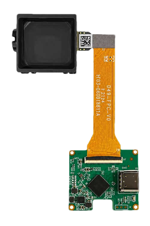
0.40″ EVF + Type-C Board
A compact digital-input direction for prototype evaluation and integration with compatible Type-C video sources.

Bring Micro OLED Image Detail Into a Compact Electronic Viewfinder
DisplayMan offers compact 0.40-inch Micro OLED multi-lens viewfinder modules for cameras, drones, thermal imagers and professional electronic imaging systems.
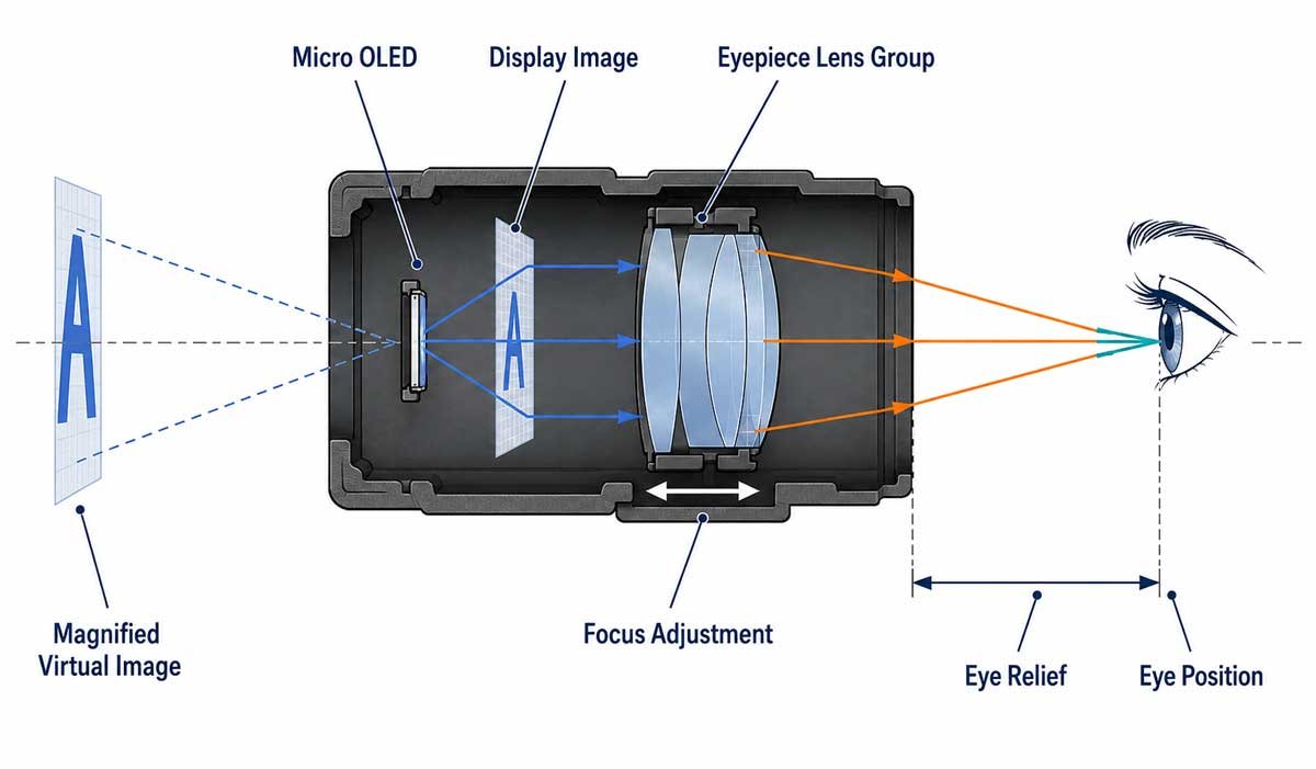
An EVF optical module combines a compact Micro OLED display, a multi-lens eyepiece, focus or diopter adjustment and a light-controlled housing. The eyepiece enlarges the microdisplay image so the operator can inspect composition, focus, menus and image data through a compact monocular viewer.
This architecture is relevant to digital cameras, drones, thermal imagers, inspection equipment and professional optical instruments where direct-view screens are impractical.
The Micro OLED creates a small real image. A matched eyepiece lens group magnifies that image and presents a virtual image to the eye at the specified eye-relief position. Moving the lens group provides focus or diopter adjustment for different users.
These configurations illustrate practical starting points for optical, interface and mechanical review. Availability and final specifications must be confirmed for each project.
A compact digital-input direction for prototype evaluation and integration with compatible Type-C video sources.
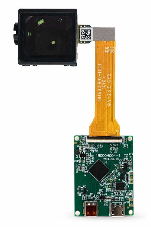
A compact HDMI-input direction for cameras, test platforms and embedded professional imaging systems.
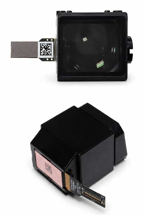
The optical-module direction for projects that will match their own driver electronics, cable routing and host architecture.
FOV, eye relief, focus range, brightness, interface and mechanical dimensions depend on the selected EVF platform and matched Micro OLED configuration.
High pixel density supports focus checking, menu text, exposure overlays and image composition after optical magnification.
Self-emissive pixels help dark scenes and high-contrast edges remain clear without a separate LCD backlight.
Fast pixel response supports moving images, while total EVF latency also depends on the sensor, processor, driver and refresh pipeline.
Micro OLED resolution must be considered together with eyepiece magnification, FOV and the detail visible to the user.
The full image should remain visible at the intended eye position, including use with glasses when required.
The adjustment mechanism must support the intended user range while maintaining stable alignment and image sharpness.
Type-C, HDMI Mini or a custom host interface must be matched to the display timing, power and mechanical space.
Display refresh, driver timing and the complete imaging pipeline must be evaluated for responsive monitoring.
Lens centering, display position, dust control, cable routing and housing tolerances affect clarity and reliability.
| Optical Direction | Typical Use | Main Strength | Main Review Point |
|---|---|---|---|
| EVF Optical Module | Cameras, drones, thermal imagers and instruments | Compact enclosed monocular viewing | Focus, eye relief, color, dust control and latency |
| Birdbath Optical Engine | AR prototypes and near-eye HUD systems | Practical reflective AR architecture | Combiner size, thickness, brightness loss and packaging |
| Pancake Optical Engine | Compact VR and high-FOV viewing systems | Folded light path reduces optical depth | Polarization, optical efficiency and source brightness |
| Other Near-Eye Optical Modules | Medical, industrial and specialized viewers | Application-driven integration | Feasibility, environment and mechanical constraints |
For most OEM projects, the practical route is to begin with an available EVF optical platform and customize the display, driver electronics, cable routing, focus structure and housing around it. A completely new eyepiece can require substantial optical design, tooling and validation.
Compare the four optical-engine directions, or return to the complete Micro OLED Optical Engines category.
It is an enclosed monocular electronic viewfinder assembly combining a Micro OLED image source with magnifying eyepiece optics, focus or diopter adjustment and a mechanical housing.
The illustrated configurations use a 0.40-inch Micro OLED direction with 1440 × 1080 reference resolution. Final display model, brightness and availability must be confirmed by project.
Not always. This page shows Type-C and HDMI Mini configurations as well as a standalone multi-lens module direction. The quoted scope must state which components are included.
Total latency depends on the sensor, image processor, video path, driver electronics, Micro OLED refresh and firmware settings. Fast pixel response alone does not guarantee low system latency.
The available adjustment range depends on the optical platform and mechanical structure. Provide the required user range for feasibility review.
Provide the application, resolution, preferred input, FOV, eye relief, focus or diopter range, refresh and latency target, available mechanical space, quantity and project stage.
Send your application, resolution, input interface, FOV, eye relief, focus range, refresh target, mechanical envelope, quantity and prototype schedule.