High Pixel Density
A large pixel count in a small display supports detailed focus checking, menus, overlays and image composition after optical magnification.

Match Micro OLED, Monocular Drivers and Optics for Your EVF Project
Create a sharp, responsive and color-consistent electronic viewfinder with DisplayMan, combining high-pixel-density Micro OLED, matched monocular driver electronics, compact EVF optical-module integration and prototype support.
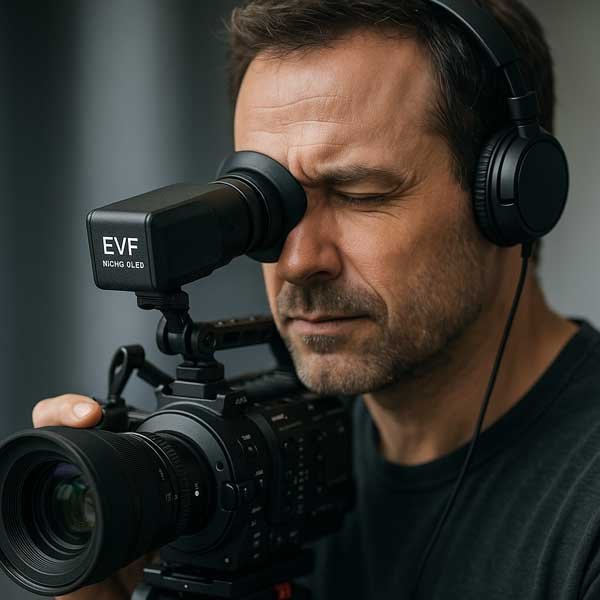
Display + Monocular Driver + EVF Optics
Match resolution, magnification, eye relief and latency as one viewing system.
Micro OLED is well suited to electronic viewfinders because a compact high-resolution display can be magnified through a small optical module while maintaining strong contrast, true black and fast response.
Final EVF quality depends on display resolution, optical magnification, eye relief, exit pupil, focus adjustment, color performance, refresh behavior, latency, driver electronics and mechanical alignment.
Do not evaluate the panel without the eyepiece optics. Match the Micro OLED size and resolution to the optical module, required perceived detail and available camera-body space.
A large pixel count in a small display supports detailed focus checking, menus, overlays and image composition after optical magnification.
Self-emissive pixels help dark scenes, exposure preview and high-contrast edges remain clear without a separate LCD backlight.
Fast pixel response supports smooth live-view motion, but complete EVF latency also depends on the sensor, processor, driver and refresh pipeline.
Eyepiece optics, focus adjustment, driver timing, color tuning and mechanical alignment determine what the photographer actually sees.
Imaging System → Monocular Driver → Micro OLED → EVF Optical Module → User’s Eye
The correct display depends on target perceived detail, eyepiece magnification, aspect ratio and mechanical space.
| Display Direction | Resolution | Brightness | Interface | EVF Starting Direction |
|---|---|---|---|---|
| 0.39″ Micro OLED | 1024 × 768 XGA | 600 cd/m² | RGB | Compact, mature EVF direction for cameras, microscopes and optical instruments. |
| 0.49″ Micro OLED | 1920 × 1080 Full HD | 1800 / 3000 / 20000 cd/m² option review | MIPI | Higher-detail 16:9 direction for professional EVF, imaging and optical R&D. |
| 0.5″ Micro OLED | 1600 × 1200 UXGA | 1000 cd/m² | MIPI | 4:3 high-resolution direction when the optical module and imaging format support UXGA. |
A higher-resolution panel may not improve perceived detail if the EVF optics, focus mechanism or usable image area cannot resolve it.
The optical module must cover the Micro OLED active area and aspect ratio without unacceptable cropping, blur or edge distortion. Display size also affects magnification and module depth.
Diopter range, lens travel, display position and mechanical tolerance must be designed together to maintain sharpness across the intended user range.
Evaluate native resolution together with optical magnification and perceived detail. Edge sharpness and uniform focus are as important as the center image.
White point, gamma, color gamut and uniformity should match the imaging workflow. Display color should not be assumed from the panel alone.
Sensor readout, image processing, transport, driver processing and panel scanout all affect the delay between scene motion and the displayed image.
Validate the complete camera-to-eye signal path at the target resolution and refresh rate.
The source may provide HDMI, Type-C, RGB, MIPI, CVBS or a project-specific signal. Confirm resolution, refresh, format, latency and available bandwidth.
The driver must supply panel timing, initialization, power, brightness control and the exact interface required by the chosen Micro OLED.
An HDMI prototype input can still require a MIPI panel-side interface. The driver board bridges these two layers.
Control display X/Y position, tilt, rotation and lens distance. Small errors can create blur, image shift or uneven focus.
Driver outline, connector height and cable bend radius must fit around the eyepiece and diopter mechanism.
Protect magnified optical surfaces from dust while managing heat from the display, driver and camera electronics.
| Project Condition | Recommended Starting Direction | Confirm Next |
|---|---|---|
| Compact mainstream EVF | 0.39″ XGA Micro OLED | Eyepiece magnification, eye relief, diopter range, RGB timing and space |
| High-detail 16:9 professional EVF | 0.49″ Full HD Micro OLED | Optical resolution, MIPI driver, refresh, color tuning and thermal load |
| High-resolution 4:3 imaging system | 0.5″ UXGA Micro OLED | Image format, optics, magnification, usable area and driver bandwidth |
| Display and eyepiece both undefined | EVF Optical Module or Near-Eye Display Solution review | Application, perceived image size, eye relief, enclosure and project stage |
| HDMI or Type-C prototype source | Monocular driver + input-interface review | Resolution, refresh, latency, power and board dimensions |
Choose the component layer when the direction is clear.
Micro OLED DisplaysParent product family for near-eye systems.Micro OLED Display ModulesCompare sizes, resolutions and interfaces.Micro OLED Driver BoardsMonocular and input-interface electronics.Micro OLED Optical EnginesEVF and other near-eye optical modules.Use when the complete system is not fixed.
Near-Eye Display SolutionDisplay + electronics + optics + mechanics review.Related Micro OLED application pages.
Micro OLED for ARAR glasses and semi-transparent optics.Micro OLED for VRHigh-resolution binocular systems.Micro OLED for FPVLow-latency goggle systems.Micro OLED for HUDNear-eye and head-mounted HUDs.Micro OLED for Medical OpticsMedical and professional instruments.Send its datasheet, supported display image size, magnification, eye relief, exit pupil, diopter range and mechanical drawing for compatibility review.
It provides high pixel density, compact size, true-black contrast and fast response for magnified near-eye viewing.
0.39-inch XGA is a compact mainstream direction, while 0.49-inch Full HD and 0.5-inch UXGA support higher-detail EVF projects. Final selection depends on optics and mechanics.
It can be suitable for many compact EVF and optical-instrument applications. Required perceived detail, magnification and focus-checking needs determine suitability.
Consider 0.49-inch Full HD when the optical module, driver electronics and imaging workflow benefit from higher 16:9 detail.
No. Panel response is only one part. Sensor readout, processing, transport, driver and scanout all contribute.
It adjusts eyepiece focus for users with different eyesight. The optical and mechanical range must be designed around the display position.
Usually yes unless the host supplies the exact panel interface, timing, power and initialization. HDMI or Type-C normally requires matching conversion electronics.
Selected projects can be reviewed as Micro OLED, monocular driver and EVF optical module integration.
Review panel characteristics together with driver settings, white point, gamma, optics and the camera imaging pipeline.
Provide application, resolution, aspect ratio, magnification, eye relief, exit pupil, diopter, optical module, input signal, space, quantity and project stage.
Send the EVF application, optical module, resolution, viewing requirements, input interface and mechanical space.
The correct EVF is engineered from the eye back to the image source.
Viewing Requirement → Eyepiece Optics → Display Size / Resolution → Driver Electronics → Mechanical Integration