High Resolution per Eye
Micro OLED places a large number of pixels in a compact area, supporting high perceived detail when each display is magnified by the VR optics.

Match Micro OLED, Binocular Drivers and Optics for Your VR Headset
Build a clearer, more compact and more immersive binocular display system with DisplayMan, combining high-resolution Micro OLED, matched driver electronics, VR optical-engine integration and prototype support.
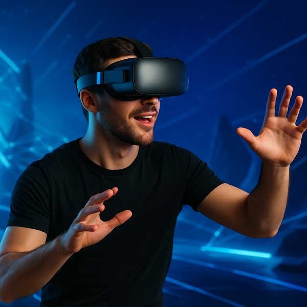
Display + Driver Electronics + VR Optics
Review the complete binocular system before freezing the Micro OLED.
Micro OLED is a strong display direction for compact VR headsets because it combines very high pixel density, true-black contrast, fast response and a small physical image source suitable for near-eye optical magnification.
A successful VR display system must balance per-eye resolution, field of view, pixel density, refresh rate, motion latency, binocular matching, optical efficiency, IPD, distortion correction, power, thermal design and mechanical volume.
Per-eye resolution alone does not determine VR image quality. Select the Micro OLED together with the lens architecture, target FOV, pixels per degree, refresh requirement and binocular mechanical design.
Micro OLED places a large number of pixels in a compact area, supporting high perceived detail when each display is magnified by the VR optics.
Self-emissive pixels provide strong contrast and fast response, helping dark scenes, fine details and moving VR imagery remain visually convincing.
Small displays can be paired with compact optical engines, including folded Pancake architectures, to reduce headset depth and overall volume.
The panel cannot compensate for unsuitable optics, low refresh rate, high motion-to-photon latency, poor distortion correction or inaccurate binocular alignment.
Most high-performance VR systems use one display per eye or a binocular arrangement that must be synchronized and mechanically aligned.
Rendering Platform → Binocular Driver Electronics → Dual Micro OLED → VR Optics → User’s Eyes
Square high-resolution Micro OLED displays are strong starting directions for compact, high-detail binocular VR. Final suitability depends on the optical engine and target system performance.
| Display Direction | Resolution | Brightness Direction | Interface | Why Consider It for VR |
|---|---|---|---|---|
| 1.03″ Micro OLED | 2560 × 2560 per display | 1800 / 3000 / 20000 cd/m² option review | MIPI | Square 2.5K-class direction suitable for compact high-resolution VR, near-eye imaging and high-FOV optical development. |
| 1.3″ Micro OLED | 3552 × 3552 per display | 4000 cd/m² | MIPI | High-end 3.5K-class direction for VR systems prioritizing per-eye detail and professional near-eye image quality. |
| 0.5″ Micro OLED | 1600 × 1200 UXGA | 1000 cd/m² | MIPI | Compact direction for selected VR viewers, prototypes and systems where optical size, aspect ratio and budget support UXGA. |
For binocular systems, distinguish panel resolution per eye from any combined marketing resolution. Also confirm whether the rendering pipeline and driver electronics can sustain the target resolution and refresh rate for both eyes.
Pancake optics fold the optical path to reduce headset thickness. They can support compact premium VR designs, but polarizers and repeated reflections may cause substantial light loss.
Conventional aspheric or Fresnel-style magnifying optics may offer a simpler and more light-efficient starting point, although the headset can be deeper and lens artifacts must be evaluated.
The lens architecture influences display size, brightness, usable image area, distortion mesh, eye box, FOV and mechanical tolerances. Freeze the display and optics together.
Panel resolution should be evaluated after considering FOV, lens magnification, usable image area and distortion correction. Higher pixel count does not automatically produce higher perceived detail.
Panel response is only part of motion performance. Rendering, transport, driver processing, scanout and tracking all contribute to motion-to-photon latency.
Pancake optics can lose significant light through polarization and multiple reflections. Source luminance must be balanced with power, thermal load, lifetime and the final eye brightness target.
Do not claim system resolution, refresh, latency, FOV or brightness from the Micro OLED datasheet alone. These are complete-system results.
Review these parameters together before freezing the Micro OLED, driver board and optical engine.
The host platform must generate left- and right-eye images at the required resolution and refresh rate. Confirm video bandwidth, transport interface, compression if any and the complete timing budget.
The binocular driver architecture must provide the selected panels with correct power, initialization, MIPI timing, refresh behavior and synchronized left/right operation.
An HDMI or Type-C source does not connect directly to a MIPI Micro OLED. The driver electronics bridge the host signal to both displays and must be validated at the target resolution and refresh rate.
Small errors in a binocular optical assembly can affect focus, stereo alignment, eye comfort and the usable FOV.
Control X/Y position, focus distance, tilt and rotation for both optical channels. The left and right image centers must remain consistent.
Mechanical IPD adjustment, lens movement and diopter strategy must not disturb cable routing, optical alignment or display clearance.
Dual displays and high-bandwidth electronics require careful FPC routing, shielding, heat spreading and separation from optical surfaces.
| Project Condition | Recommended Starting Direction | What to Confirm Next |
|---|---|---|
| Compact premium VR using Pancake optics | Dual 1.03″ 2560 × 2560 Micro OLED | Optical efficiency, polarization, FOV, refresh, distortion, IPD and thermal load |
| High-end VR prioritizing maximum per-eye detail | Dual 1.3″ 3552 × 3552 Micro OLED | Rendering bandwidth, driver capability, optics, headset volume and power |
| Compact viewer or early prototype | 0.5″ UXGA or another compatible module | Required detail, FOV, aspect ratio, optics and budget |
| Customer needs a complete Pancake display module | Pancake Optical Engine review | Target FOV, eye box, eye relief, IPD, brightness and mechanical envelope |
| Customer needs HDMI or Type-C prototype input | Binocular Driver Board and HDMI / Type-C interface review | Total resolution, refresh rate, source format, power and board space |
| Optics and display are both undefined | Near-Eye Display Solution review | Application, target FOV, resolution, headset size, project stage and budget |
Choose the hardware layer when the component direction is already clear.
Micro OLED DisplaysParent Micro OLED product family for near-eye and optical systems.Micro OLED Display ModulesCompare Micro OLED sizes, resolutions, brightness and interfaces.Micro OLED Driver BoardsMonocular, binocular, HDMI / Type-C and custom-interface electronics.Micro OLED Optical EnginesPancake, Birdbath, EVF and other near-eye optical directions.Use the solution page when the complete VR system architecture is not fixed.
Near-Eye Display SolutionDisplay + electronics + optics + mechanics system review.Related Micro OLED application engineering pages.
Micro OLED for ARMicro OLED image-source selection for AR glasses and semi-transparent optics.Micro OLED for EVFDisplay selection for cameras, drones and electronic viewfinders.Micro OLED for FPVLow-latency binocular Micro OLED systems for FPV goggles.Micro OLED for HUDMicro OLED image-source review for near-eye and head-mounted HUD systems.Micro OLED for Medical OpticsMedical, microscope and professional optical-instrument integration.Send the optical datasheet, FOV, eye box, eye relief, distortion data, display image-size requirement, mechanical drawing and preferred video input. This is the fastest route to compatibility review.
Micro OLED combines very high pixel density, compact physical size, true-black contrast and fast response, making it suitable for high-resolution near-eye VR systems.
The 1.03-inch 2560 × 2560 and 1.3-inch 3552 × 3552 directions are strong starting points for high-resolution binocular VR. Final selection depends on optics, FOV, refresh, headset volume, power and budget.
Per-eye resolution is the native pixel matrix shown to each eye. It should not be confused with a combined left-plus-right marketing resolution.
Suitability depends on field of view, lens magnification, usable image area, distortion correction and the required pixels per degree. Resolution alone cannot determine the final perceived detail.
A 1.3-inch 3552 × 3552 Micro OLED is relevant when the project prioritizes high per-eye detail and the rendering, driver, optical, power and mechanical systems can support it.
Pancake optics fold the optical path to reduce headset depth. However, their polarization and multiple reflections can reduce optical efficiency, so brightness, thermal load and optical coatings must be reviewed together.
No. Panel response is only one part of motion-to-photon latency. Tracking, rendering, transport, driver processing and scanout also contribute.
Yes. Left and right displays must receive correctly timed images, panel initialization and refresh behavior. Synchronization requirements should be confirmed with the complete rendering and driver architecture.
VR lenses distort the image. The rendering pipeline normally pre-warps the image using a lens-specific distortion model so the user perceives the intended geometry through the optics.
Interpupillary distance determines the spacing between the optical centers for the user’s eyes. Incorrect IPD can reduce clarity and visual comfort.
Selected projects can be reviewed as Micro OLED displays, binocular driver electronics, optical engines and mechanical integration. Final scope depends on the required performance and project stage.
Provide the VR application, per-eye resolution, refresh target, FOV, pixels per degree if known, eye box, eye relief, IPD range, optical architecture, input signal, mechanical space, quantity and project stage.
Send the per-eye resolution, FOV, refresh target, optical architecture, IPD range, input interface and available mechanical space.
For VR, select the display around perceived detail and the complete binocular system.
Use Case → FOV / PPD → Optics → Per-Eye Resolution → Refresh / Latency → Driver Electronics → Binocular Mechanics