High Resolution in a Small Area
Micro OLED uses a silicon backplane to achieve very high pixel density in a compact physical display, which is valuable when the image will be optically magnified.

Match Micro OLED, Driver Electronics and Optics for Your AR Project
Develop a brighter, clearer and more compact augmented-reality display system with DisplayMan, combining high-pixel-density Micro OLED, matched driver electronics, AR optical-engine integration and prototype support.
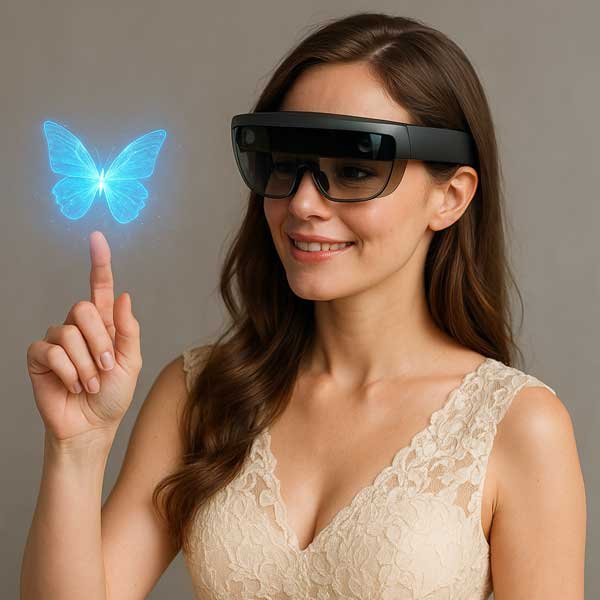
Display + Driver Electronics + AR Optics
Match brightness, FOV and optical efficiency before freezing the Micro OLED.
Micro OLED is a strong image-source technology for compact AR glasses because it combines high pixel density, small physical size, high contrast and fast response in an OLED-on-Silicon platform.
However, selecting a Micro OLED for AR is not only a display decision. The final result depends on the complete chain of display brightness, optical architecture, field of view, eye box, eye relief, driver electronics, mechanical volume, power and thermal design.
Do not choose the Micro OLED from resolution alone. Start from the optical architecture and final viewing requirement, then select display size, resolution and brightness around the complete AR system.
Micro OLED uses a silicon backplane to achieve very high pixel density in a compact physical display, which is valuable when the image will be optically magnified.
True black, strong contrast and fast response help near-eye systems produce clear text, graphics and video without a separate LCD backlight.
The small display footprint allows integration with Birdbath, prism, Pglass-style and project-specific AR optical systems.
Final AR image quality is determined by both the Micro OLED and the optical system that magnifies, redirects and combines the image with the user’s view of the real world.
A practical AR display system contains several layers. The Micro OLED should be selected only after the optical and mechanical direction is understood.
Host → Driver Board → Micro OLED → AR Optical Engine → User’s Eye
The correct Micro OLED depends on the optical engine, but two Full HD directions are especially useful starting points for many AR projects.
| Display Direction | Resolution | Brightness Direction | Interface | Why Consider It for AR |
|---|---|---|---|---|
| 0.49″ Micro OLED | 1920 × 1080 Full HD | 1800 / 3000 / 20000 cd/m² option review | MIPI | Compact Full HD image source with multiple brightness directions for AR, HUD, EVF and optical R&D. |
| 0.6″ Micro OLED | 1920 × 1080 Full HD | 6000 cd/m² | MIPI | Useful when the optical architecture benefits from a physically larger FHD display and stronger brightness direction. |
| 0.5″ Micro OLED | 1600 × 1200 UXGA | 1000 cd/m² | MIPI | Relevant for selected AR and optical systems where the aspect ratio and resolution fit the optical architecture. |
0.49″ and 0.6″ are strong AR candidates, but final selection should follow the target FOV, optical efficiency, available mechanical space and required eye brightness.
A practical direction for AR prototypes and selected semi-transparent near-eye systems. Review Micro OLED brightness, FOV, combiner size, eye relief and overall thickness together.
Useful for selected compact smart-glasses architectures where display size, mechanical layout, weight and optical path must be tightly integrated.
Micro OLED can be evaluated as the image source for project-specific waveguide systems. Compatibility depends on the customer’s coupling optics, brightness target, FOV and mechanical architecture.
In AR, the optical architecture often determines the required Micro OLED brightness and physical size. Do not freeze the display before confirming the optical direction.
A very bright Micro OLED can still produce a dim AR image if the optical path has high loss. Conversely, an enclosed or more efficient optical system may not require the maximum available panel brightness.
The correct brightness target should be evaluated after the complete optical path, including ambient-light conditions and the final combiner or waveguide architecture.
AR is a system-level application. These parameters should be reviewed together before the display and optics are frozen.
The host device may output HDMI, Micro HDMI, Type-C, MIPI or another embedded video signal. This is not necessarily the same interface used by the Micro OLED panel.
The driver board must provide the timing, initialization, power and panel-side interface required by the selected Micro OLED. Compact AR products may also require a rigid-flex PCB or project-specific connector layout.
A customer may request Type-C or HDMI while the Micro OLED uses MIPI. The driver electronics bridge these two layers.
AR products are often constrained more by physical volume and weight than by display specifications alone.
The Micro OLED must remain accurately positioned relative to the lens, prism or combiner. Small alignment errors can affect clarity, distortion and image position.
Driver-board outline, connector height, FPC direction and cable bends must fit around the optical engine and glasses frame.
High-brightness operation can increase power and heat. Thermal behavior should be reviewed together with enclosure material, battery strategy and user comfort.
| Project Condition | Recommended Starting Direction | What to Confirm Next |
|---|---|---|
| Compact AR prototype using Birdbath optics | 0.49″ Full HD Micro OLED | Required eye brightness, FOV, eye relief, combiner size and board space |
| AR system requiring stronger source brightness | 0.6″ Full HD or high-brightness 0.49″ option review | Optical efficiency, thermal load, power and mechanical size |
| Compact prism / Pglass-style smart glasses | 0.49″ Micro OLED or other compatible compact Micro OLED | Optical-module interface, weight, enclosure and cable routing |
| Customer already has waveguide optics | Micro OLED matched to waveguide input requirements | Coupling optics, FOV, brightness, image size and mechanical position |
| Embedded processor already outputs MIPI | Direct / custom MIPI electronics review | Panel timing, initialization, power and connector compatibility |
| Customer needs HDMI or Type-C prototype input | Micro OLED + matching driver board | Resolution, refresh rate, board size, power and firmware |
| Optics and display are both undefined | Near-Eye Display Solution review | Application, FOV, eye box, eye relief, mechanics and target budget |
Choose the hardware layer when the component direction is already clear.
Micro OLED DisplaysParent Micro OLED product family for near-eye and optical systems.Micro OLED Display ModulesCompare available Micro OLED sizes, resolutions and brightness directions.Micro OLED Driver BoardsMatch HDMI, Type-C, MIPI and other signal paths to the selected display.Micro OLED Optical EnginesBirdbath, Pancake, EVF and project optical-module directions.Use the solution page when the AR system architecture is not yet fixed.
Near-Eye Display SolutionComplete display + electronics + optics + mechanics review for near-eye systems.Related Micro OLED application engineering pages.
Micro OLED for VRHigh-resolution binocular Micro OLED and compact near-eye optical architectures.Micro OLED for EVFMicro OLED selection for cameras, drones and electronic viewfinders.Micro OLED for FPVLow-latency binocular Micro OLED systems for FPV goggles.Micro OLED for HUDHigh-brightness Micro OLED image-source review for HUD systems.Micro OLED for Medical OpticsMicro OLED integration for medical, microscope and professional optical instruments.Send the optical datasheet, FOV, eye box, eye relief, mechanical drawing or prototype photos together with your required video input. This is the fastest route to Micro OLED compatibility review.
Micro OLED provides very high pixel density, compact physical size, strong contrast, true black and fast response, making it a strong image-source direction for compact near-eye AR systems.
0.49-inch Full HD and 0.6-inch Full HD are strong starting points for many AR projects. Final selection depends on brightness, field of view, optical architecture, mechanical space and power requirements.
Yes. The 0.49-inch 1920 × 1080 direction combines compact size, Full HD resolution and multiple brightness directions, making it relevant for AR, HUD, EVF and optical R&D projects.
The 0.6-inch 1920 × 1080 direction is useful when the optical system benefits from a physically larger image source and stronger brightness direction.
There is no single correct brightness value. Required panel brightness depends on losses through the optical engine, combiner, polarizers, mirrors, lenses or waveguide. Final eye brightness should be evaluated through the complete optical path.
Yes. Birdbath is a practical optical direction for AR prototypes and selected semi-transparent near-eye systems. Brightness, field of view, eye relief, combiner size and mechanical thickness should be reviewed together.
Micro OLED can be evaluated as the image source for project-specific waveguide systems, but compatibility depends on the customer’s optical architecture, input coupling, brightness requirement and mechanical design.
Usually yes unless the host electronics already provide the exact panel-side interface, timing, power and initialization required by the Micro OLED. HDMI or Type-C inputs normally require a matching driver board.
Both matter, but neither should be selected alone. Resolution, brightness, field of view, eye box, optical efficiency, display size and mechanical volume must be balanced as one system.
Eye box is the area in which the user’s eye can move while still seeing the complete virtual image. A small eye box can make AR glasses difficult or uncomfortable to use.
Selected projects can be reviewed as a combination of Micro OLED display, driver electronics, optical engine and mechanical integration. Final scope depends on the optical architecture and project requirements.
Provide the target application, preferred display size if known, resolution, brightness, field of view, eye box, eye relief, optical architecture, mechanical size, input signal, quantity and prototype or production stage.
Send the AR application, optical architecture, FOV, eye box, eye relief, brightness requirement, input interface and mechanical space.
For AR, the correct Micro OLED is selected around the optics — not the other way around.
Optical Architecture → FOV → Display Size → Resolution → Brightness → Driver Electronics → Mechanical Integration