
Nine Micro OLED Platforms for Near-Eye and Optical Systems
Compare current Micro OLED display modules from DisplayMan, from compact 0.23″ products to 1.30″ 3.5K platforms. Select by resolution, brightness, interface, optics and final application.
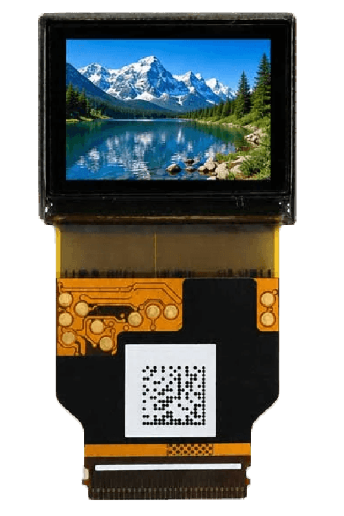
Explore a product below, or send your application requirements and let us help you choose.
DisplayMan supplies Micro OLED display modules — also known as OLED-on-Silicon, OLEDoS or OLED microdisplays — for AR glasses, VR headsets, electronic viewfinders, FPV goggles, HUD systems, microscopes, thermal imaging viewers, medical optics and other compact optical products.
This page focuses on the Micro OLED display module itself: available size directions, resolution, brightness, panel interface and product-selection logic.
Micro OLED Display Modules are the image-source products. Driver boards and optical engines are related but separate product categories. Select the display module first, then match the driver electronics and optics around the final near-eye system.
Micro OLED display modules provide compact OLED-on-Silicon image sources for magnified near-eye and professional optical systems. The following characteristics are especially relevant when comparing the nine available module platforms.
Brightness, resolution, interface, refresh rate, power consumption and operating conditions vary by model. Select the display module together with the driver electronics and optical architecture.
DisplayMan’s current public portfolio is organized into nine base product platforms. Different brightness, FPC and derived active-area configurations are not counted as separate products.
The 0.40″ direction belongs to the 0.49″ platform, while the 0.57″, 0.62″ and 0.83″ directions belong to the 1.03″ platform.
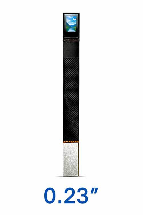
Typical use: Compact near-eye viewers, miniature optical instruments and lightweight wearable systems.
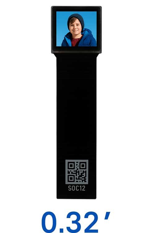
Typical use: FPV goggles, compact near-eye modules and small optical systems.
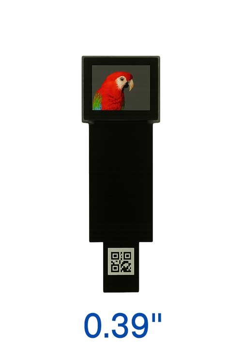
Typical use: Camera EVF, microscopes and professional optical viewfinders.
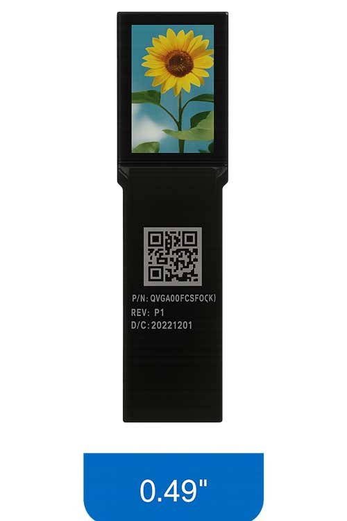
Typical use: AR glasses, HUD systems, EVF modules and optical R&D.
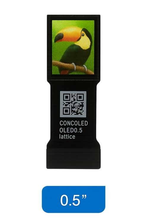
Typical use: AR and VR headsets, medical imaging and optical R&D.
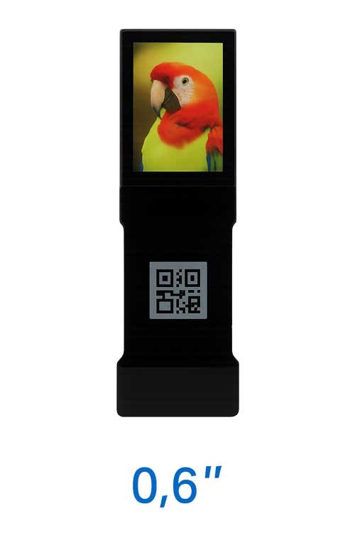
Typical use: AR headsets, HUD, EVF and professional optical systems.
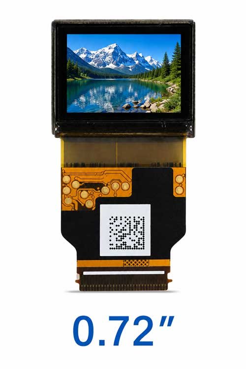
Typical use: High-detail EVF, head-mounted displays and professional optical instruments.
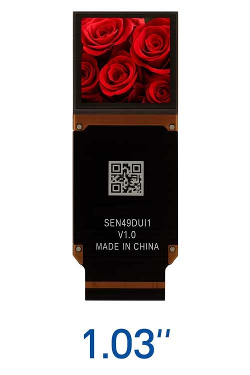
Typical use: VR headsets and compact high-FOV binocular optical systems.
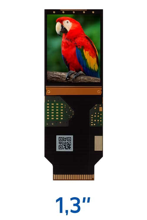
Typical use: Premium VR, simulation and high-resolution professional imaging.
Click a product image or title to open its detailed page. Confirm the exact model, brightness, interface, FPC direction, supply status and driver compatibility before design-in.
Use this table to identify the base platform first. Then confirm the exact brightness, cable, driver and optical configuration on the individual product page.
| Base Size | Resolution | Brightness Direction | Interface | Main Model / Series | Platform Note |
|---|---|---|---|---|---|
| 0.23″ | 640 × 400 | 3000 / 6000 / 10000 cd/m² | MIPI + I²C | TAS023VGH01 | The smallest independent platform; full-color and monochrome configurations provide different brightness levels. |
| 0.32″ | 800 × 600 | 400 / 2000 cd/m² | MIPI / RGB | SY032WEM01 series | Choose when compact size and SVGA detail are more important than Full HD resolution. |
| 0.39″ | 1024 × 768 | 600 / 20000 cd/m² | RGB | TAS039XGH01 series | A compact native XGA platform with standard and high-brightness configuration directions. |
| 0.49″ | 1920 × 1080 | 1800 / 3000 cd/m² | MIPI | SY049WDM / SY049LDM series | 1800 cd/m² supports short or long FPC; 3000 cd/m² uses long FPC. The 0.40″ direction is derived from this platform. |
| 0.50″ | 1600 × 1200 | 1000 cd/m² | MIPI | SY050WGM01 | A native 4:3 UXGA platform when extra vertical resolution suits the optical architecture. |
| 0.60″ | FHD / SXGA / SVGA | 200 / 3000 / 6000 cd/m² | MIPI / RGB | SY060 series | One base size with several resolution, interface and brightness configurations; confirm the correct model. |
| 0.72″ | 1920 × 1200 | 2000 cd/m² | 4-lane MIPI + I²C | SY072WCM series | An independent native WUXGA platform with a 16:10 image format and up to 60 Hz operation. |
| 1.03″ | 2560 × 2560 | Current: 1000 cd/m² | MIPI | SY103WAM19 | Current model SY103WAM19. Former 1800, 3000 and 20000 cd/m² versions are discontinued; 0.57″, 0.62″ and 0.83″ are derived directions. |
| 1.30″ | 3552 × 3552 | 1600 cd/m² | MIPI / I²C | SY130LJM01 | The largest native platform when maximum square-format resolution is the priority. |
Do not select a Micro OLED module from resolution alone. The display is part of an optical system, so the correct model depends on how the image will be magnified, how much light the optics lose, and how much physical space is available.
Application → Optical Architecture → Field of View → Display Size → Resolution → Brightness → Interface → Driver Board → Mechanical Integration
In enclosed optical paths, extremely high panel brightness may not be necessary. Image quality, contrast, resolution and thermal behavior may be more important than maximum luminance.
Combiners, beam splitters, polarizers and folded optical paths can reduce the light reaching the eye. High-brightness Micro OLED directions become more relevant when the optical architecture has significant loss.
The brightness value on the Micro OLED specification describes the display source, not the final image after lenses, mirrors, polarizers, combiners or other optical elements.
A higher-resolution microdisplay does not automatically create a better near-eye product. The optical engine must be able to resolve the additional detail, and the final FOV and magnification determine how much pixel density the user actually sees.
Useful for EVF, FPV, compact viewers and optical instruments where size and system simplicity are more important than Full HD-class detail.
Strong mainstream directions for AR, HUD, EVF, FPV and many OEM near-eye products requiring higher perceived detail.
Relevant for high-FOV, binocular VR, premium imaging and advanced optical systems where very high pixel density is justified.
The Micro OLED module’s panel interface is not the same as the customer’s external video-input connector.
| Interface Layer | Typical Direction | What It Means |
|---|---|---|
| Micro OLED Panel Interface | MIPI / RGB | The native electrical interface used by the selected microdisplay module. |
| Driver Electronics | Model-specific conversion / control | Matches the host signal to the Micro OLED panel and manages display timing / control. |
| External Video Input | HDMI / Micro HDMI / Type-C / CVBS / other project input | Normally provided through a matching driver board rather than directly by the Micro OLED panel. |
A Micro OLED display module normally cannot be connected directly to HDMI or Type-C. If your prototype needs an external video input, select the Micro OLED module and driver board as a matched system.
Compact FHD and high-brightness directions can be reviewed with Birdbath, prism, combiner or other AR / HUD optical architectures.
High-resolution 2.5K and 3.5K directions are relevant for binocular systems, high FOV and compact Pancake optical architectures.
Compact XGA, Full HD and higher-resolution modules support cameras, drones, viewfinders and professional imaging systems.
Compact Micro OLED modules provide high contrast, fast response and low-latency image-source directions for real-time FPV viewing.
Micro OLED can serve as the image source inside microscope eyepieces, medical viewers and specialized optical instruments.
Compact self-emissive Micro OLED modules can be integrated into thermal imagers, inspection equipment and portable optical instruments.
| Product Category | What It Contains | Choose It When |
|---|---|---|
| Micro OLED Display Module | OLED-on-Silicon microdisplay / image source | You already have the required electronics and optical architecture or are selecting the panel first. |
| Micro OLED Driver Board | Signal conversion, timing, control, power and external input support | You need HDMI, Type-C, RGB, MIPI or another host-interface path for prototype or OEM integration. |
| Micro OLED Optical Engine | Microdisplay combined with lenses / prisms / mirrors / optical mechanics | You need a usable virtual image module rather than the display panel alone. |
| Near-Eye Display Solution | Display + electronics + optics + mechanics system review | You know the final product but do not yet know which display, driver and optical architecture to use. |
A fully custom Micro OLED semiconductor panel from zero is normally not practical for ordinary OEM projects because of semiconductor-level development cost and lead time. The practical route is to select an available Micro OLED display module and customize the surrounding system.
Continue through the Micro OLED product cluster.
Micro OLED Displays Parent topic page for display modules, driver boards and optical engines. Micro OLED Driver Boards Monocular, binocular, HDMI, Type-C and custom interface electronics. Micro OLED Optical Engines Birdbath, Pancake, EVF and other near-eye optical module directions.Use the system page when the project requires more than a display module.
Near-Eye Display Solution Display + driver electronics + optics + mechanics integration for near-eye products.Start from the final device when the correct module is not yet known.
Micro OLED for AR Brightness, optical efficiency and compact integration for augmented reality. Micro OLED for VR High resolution, binocular matching and immersive near-eye systems. Micro OLED for EVF Fine detail, contrast and fast response for electronic viewfinders. Micro OLED for FPV Low-latency image pipelines and compact FPV goggles. Micro OLED for HUD Near-eye and head-mounted HUD image-source selection. Micro OLED for Medical & Optical Instruments Microdisplays for medical viewers, microscopes and professional optical systems.Send the final application and optical requirement first. DisplayMan can compare the available Micro OLED modules and recommend the most practical display direction before driver-board and optical-engine selection.
Open an individual product page for model details, specifications and application guidance.
A Micro OLED display module is a very small OLED-on-Silicon microdisplay used as the image source inside near-eye and optical systems such as AR glasses, VR headsets, EVF, FPV goggles, HUD systems and optical instruments.
No. Standard OLED is normally a direct-view display built for phones, monitors or signage. Micro OLED is built on a silicon backplane and is designed for very high pixel density in optical systems.
Choose the size together with resolution, brightness, interface, optical magnification, field of view and mechanical space. The physical display size should not be selected independently from the optical engine.
0.49-inch and 0.6-inch Full HD directions are strong starting points for many AR projects, but the correct choice depends on brightness, optical efficiency, field of view, eye box, mechanical size and the selected optical architecture.
High-resolution directions such as 1.03-inch 2560 × 2560 and 1.3-inch 3552 × 3552 are relevant for demanding VR and high-FOV systems. Final selection also depends on refresh rate, binocular architecture and optics.
Not necessarily. The display module and HDMI or Type-C driver electronics are separate system elements and must be matched to the selected Micro OLED model.
Usually no. A suitable driver board or signal-conversion architecture is required between the host source and the Micro OLED interface.
The public reference directions in this product family include MIPI and RGB. HDMI, Type-C and other external source inputs are normally handled through a matching driver board.
No. Required brightness depends on the optical architecture and total optical loss. Enclosed EVF or VR systems may need less panel brightness than AR, HUD or Pancake systems with higher optical loss.
No. Resolution should match display size, field of view, optical magnification and the final application. Higher resolution increases system requirements and may provide little benefit if the optics cannot resolve the additional detail.
Usually no. Micro OLED projects should start from available semiconductor display platforms. Customization is normally focused on driver electronics, cable, optical engine, mechanics and system integration.
Provide the application, preferred display size if known, required resolution, brightness, interface, field of view, optical engine requirement, mechanical space, quantity and project stage.
Send the application, preferred display size, resolution, brightness, optical requirement, host interface, quantity and project schedule. DisplayMan will compare the nine current module platforms.
The Micro OLED module, driver electronics, optical engine, mechanical structure, thermal design and host interface should be evaluated as one complete near-eye display system.