
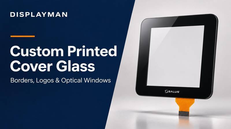
Custom cover-glass printing determines more than the color of a touchscreen’s border. It defines what users see, what the glass conceals and where light must pass through. A black frame, white logo, clear camera window and hidden indicator window can share one continuous piece of glass, but each needs a different drawing requirement.
For optical functions, our first choice is usually a fully transparent window in intact glass. In the camera and light-transmission projects we normally handle, this can replace almost all requests for a physical hole—and can be the better construction. A translucent window addresses a different requirement: hide the feature when unlit while allowing the required light through. Neither a clear window nor a physical hole delivers that same combination.
This guide focuses on printed cover glass for add-on capacitive touch assemblies, including G+G structures. It does not cover special openings within an LCD or OLED display. For touch-integration structures, see our OGS vs. On-Cell vs. In-Cell guide.
1. Start with a Front View and a Defined Display Area
Before discussing colors, identify the user-facing side and the display active area, or AA. On a typical assembly, the central viewing window sits over the display, while the printed border surrounds it. Auxiliary windows for cameras, indicators or sensors are usually positioned in that border, outside the display AA.
This distinction matters because a window in the printed cover is not a hole through the display underneath. A transparent region over an opaque component does not create an unobstructed optical path.
Start with a front-view drawing showing the cover outline, display AA and required printed features. Then identify the rear surface where printing will be applied. Using one agreed viewing direction prevents a logo, asymmetric border or camera window from appearing on the wrong side of the finished product.
2. Black Borders: Decide What Must Be Hidden
The black border creates the visible frame around the screen and conceals areas that should not be seen through the cover. Depending on the assembly, these can include touch routing, adhesive edges or parts of the enclosure.
Border width should follow that concealment requirement and the display position. An attractive narrow frame is not successful if it exposes internal parts. Conversely, an unnecessarily wide printed area can obstruct the intended image.
Confirm the printed viewing-window dimensions against the actual display position, allowing for agreed assembly tolerances. Keep the display AA and the printed-window boundary as separate drawing references, even when they are designed to align closely.
Also define the appearance of the black region. The agreed color and opacity should be judged through the front glass, as the user will see them. Where bright components sit behind the border, include that lighting condition in sample approval so unintended light leakage is not missed.
3. Rear-Surface Printing Protects Logos from Direct Wear
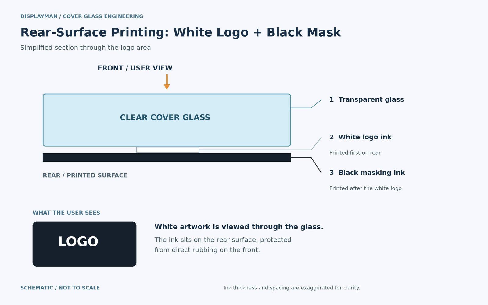
In our illustrated G+G capacitive-touch example, the cover glass itself is transparent. The white logo is screen-printed onto its rear surface first, followed by the black layer behind it. From the front, the user sees the white logo through the glass against the black border.
This sequence is important: the white image must remain visible from the viewing side. The artwork and layer order therefore need to be agreed together, rather than treating the logo as a label added after the black frame is finished.
The practical durability advantage is that fingers and normal front-surface wiping contact the glass, not the printed logo. The glass shields the rear printing from direct abrasion during use. That is a clear reason to prefer this construction over exposed front-surface decoration where the design permits it.
It is not a promise that every ink system is immune to all chemicals or processing conditions. Confirm ink adhesion, curing and compatibility with subsequent assembly operations through the agreed manufacturing process.
What to supply for a printed logo
Provide vector artwork, its final dimensions, color reference and position relative to the drawing datums. Convert fonts to outlines or supply the required font information. A small screenshot may explain the idea, but it should not become the only production artwork.
Check the logo from the front after printing. Color, fine details and alignment should be accepted on the finished glass sample, not solely on a monitor rendering.
4. Clear Windows: Keep the Glass, Remove the Masking
A clear window is a transparent region in the printed design. The glass remains continuous; the opaque masking is omitted from the specified area. It is not a drilled opening.
The main display window is one example. A small clear region in the border can also provide an optical path for a camera or another component requiring visible-light transmission.
For a camera behind the cover, a clear window is our preferred starting point and is usually more useful than an exposed physical opening. The continuous glass helps protect the internal lens from direct contact with grease and dirt, while avoiding the additional glass-machining step and its associated cracking risk. The exterior glass still needs appropriate cleaning; a clear window does not make the optical path maintenance-free.
Specify the window position and dimensions against the camera’s actual location. Check that the printed edge does not obstruct the required field of view, including the expected alignment variation. Evaluate image quality with the intended glass and assembled camera; appearance to the naked eye alone does not establish camera performance.
A camera, indicator and optical sensor should not automatically share the same window specification. State the component’s function so the design can be reviewed against what must pass through the glass.
5. Translucent Windows: A Specialist Optical-Printing Requirement
A clear window leaves the glass transparent by omitting the opaque masking from the required area. A translucent window does something more demanding: it must blend into the surrounding border when unlit while transmitting the required light when illuminated.
This is functional optical printing, not simply a decorative variation of the black frame. Hidden-until-lit effects are commonly described as dead-front printing. The required result depends on both the printed glass and the lighting or optical component behind it.
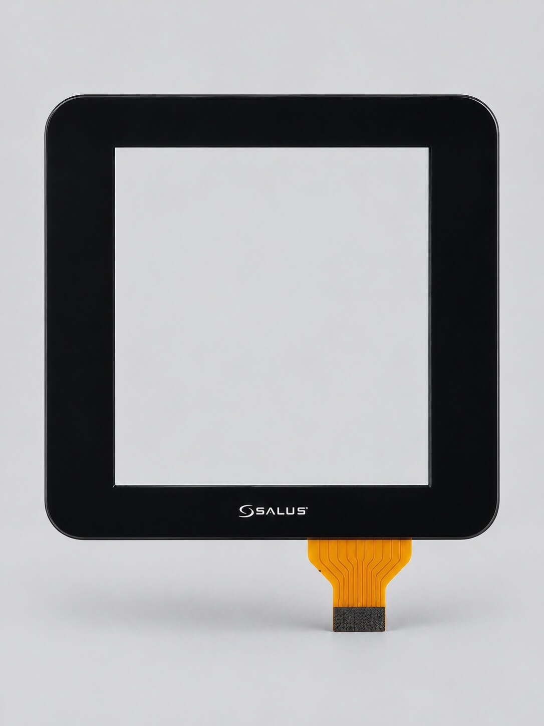
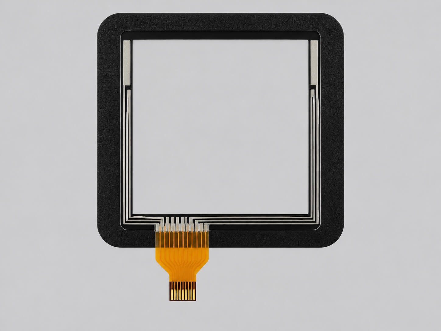
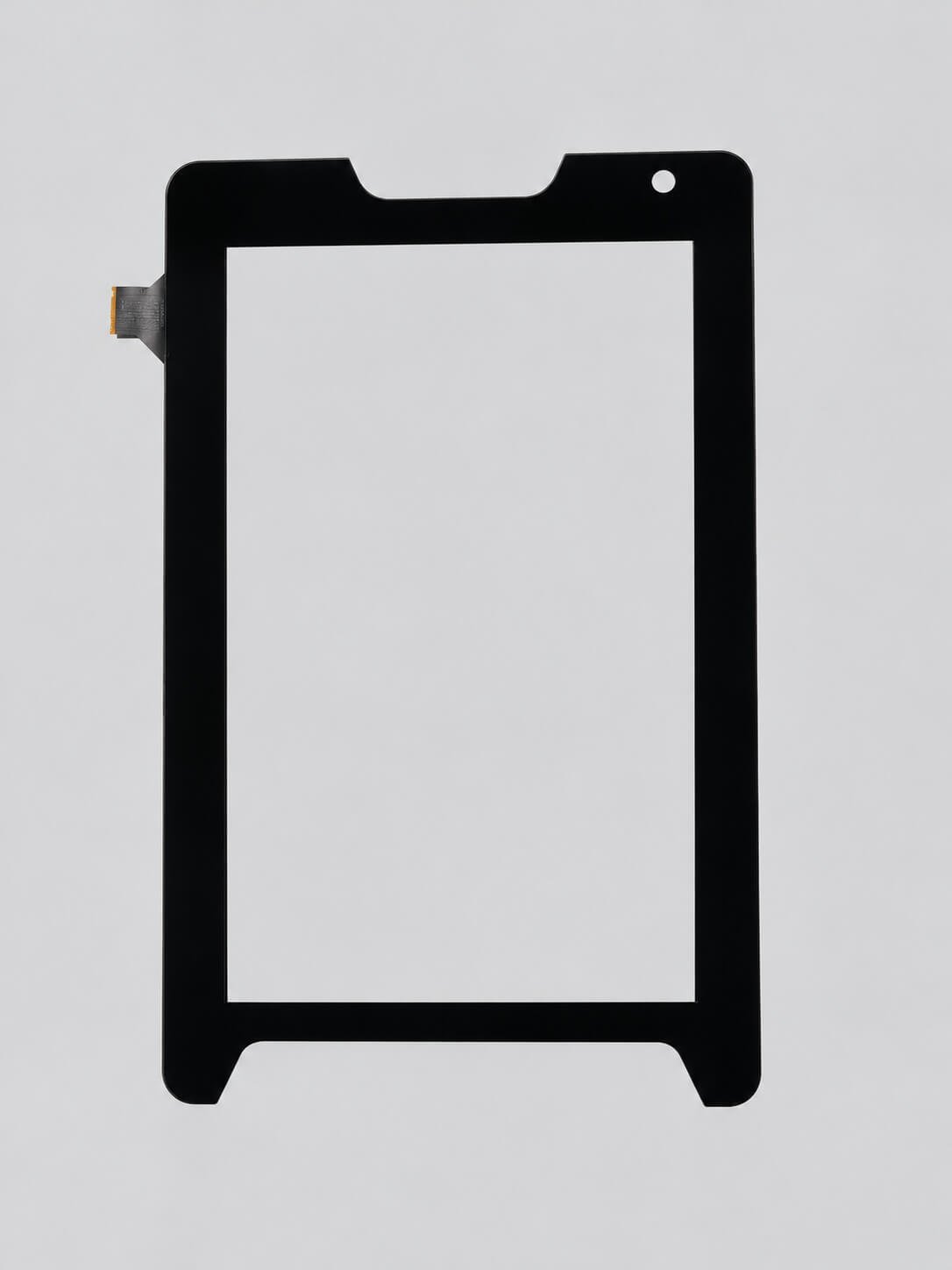
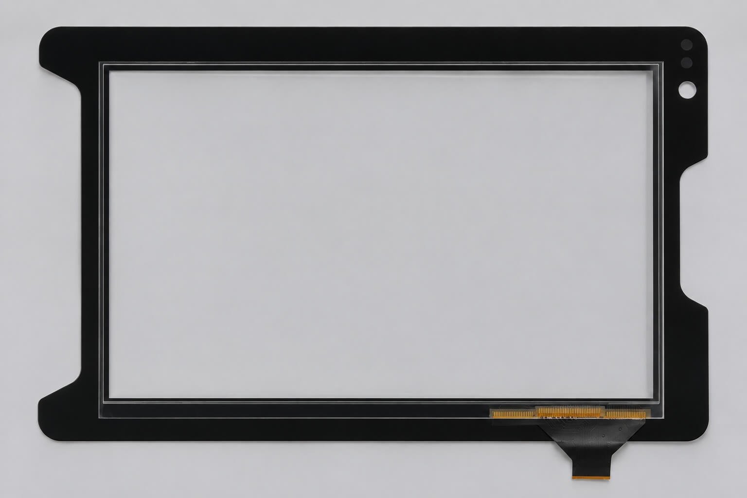
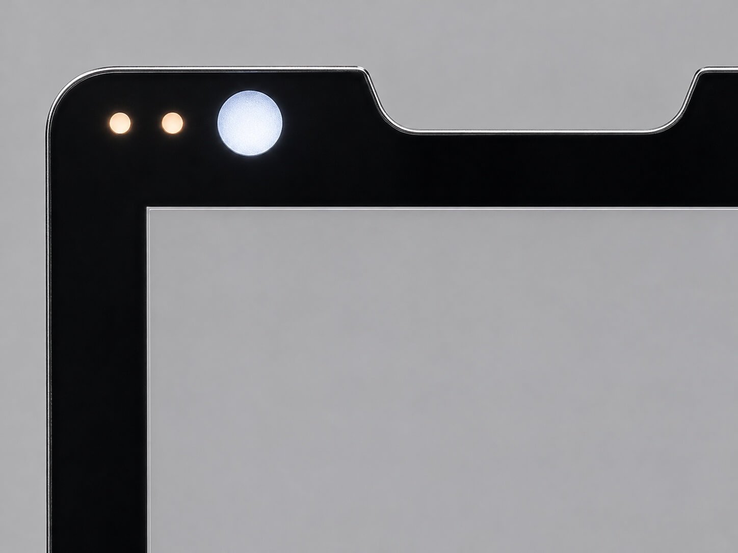
Our three photographs show the difference
The supplied photographs show the same assembly under three observation conditions:
| Observation | What the sample shows |
|---|---|
| Front view under normal lighting | The large clear viewing window is apparent; the two small translucent windows blend into the black border. |
| Rear view | The positions of the two small windows can be faintly distinguished. |
| Light applied from behind | The two small windows become clearly visible as light-transmitting areas. |
This is a practical example of the intended concealment-and-transmission effect. The glass has not changed state and no physical holes have appeared: backlighting reveals the light transmitted through the printed regions.
Use all three views to explain the design requirement. The front view establishes the appearance customers normally see; the rear view identifies the window locations; the illuminated view demonstrates that those regions transmit light. The photographs show the effect, but do not establish a measured transmission percentage or a particular ink formulation.
Why it requires specialist manufacturing
The difficult requirement is achieving concealment and transmission together. Too much transmission can reveal a window or the component behind it when it should remain hidden. Too little can leave an illuminated feature too dim.
The window must also match the surrounding border closely enough in the unlit state and transmit light consistently when lit. Pinholes, bright or dark spots and uneven printing may become obvious under backlighting even when the surface looks acceptable in ordinary room light.
Specialist manufacturers therefore specify and inspect transmission or optical density as well as cosmetic appearance. Abrisa publishes dead-front glass with defined transmission levels, while Cat-i’s printed-glass inspection criteria separately address transmission, pinholes and backlit defects. These are examples of professional process control, not specifications automatically applicable to our sample.
Cost and risk are different from drilling
In our sourcing experience, demanding translucent-window requirements can be very expensive compared with a clear window and need a specialist supplier. The extra scope is optical-print development and control, supported by samples and inspection—not glass drilling. Quote these features separately rather than assuming that a small window is a low-cost detail.
The glass remains intact, avoiding drilling-induced cracking. That does not mean there is no manufacturing rejection risk: transmission, color matching, uniformity or adhesion can still fail acceptance.
A translucent window is justified when the feature must disappear into the black border when unlit and remain functional when illuminated. A fully transparent window exposes the region; a physical hole removes the protective glass. Neither is a functional substitute for the specified hidden-until-lit appearance. If concealment is unnecessary, choose the simpler clear window.
Specify the function before the transmission target
For an indicator or illuminated symbol, approve both the unlit appearance and the lit result with the intended light source. Agree viewing conditions and any required transmission, color and uniformity limits before production. A flashlight can demonstrate the effect, but cannot define the finished product’s brightness.
For a sensor window, identify the sensor and required wavelength band. A visible-light dead-front window and an IR-transmitting window are not automatically interchangeable. Confirm that requirement without inferring it from the window’s appearance.
6. Shaped Outlines, Notches and Rounded Corners
A custom cover does not have to be a simple rectangle. Our example has recesses cut into the outer edges and rounded transitions. These are external-profile features, distinct from enclosed holes drilled through the glass.
In our project experience, custom outlines and edge notches generally add machining cost, but are usually more straightforward to produce than enclosed through-holes. The actual difficulty depends on the geometry: define notch width, depth, internal radii and remaining glass sections on the drawing. Do not treat an edge recess and a through-hole as interchangeable manufacturing requirements.
Choose the profile to fit the enclosure or provide the required clearance. Agree the outline and edge finish before sampling, rather than estimating the shape from a photograph.
7. Clear Window or Physical Hole?
For the features discussed here, our practical difficulty ranking is: translucent window first, physical through-hole second, fully transparent window simplest. This reflects our project and sourcing experience. Optical-printing difficulty and mechanical breakage risk are different considerations.
| Feature | Difficulty and risk | Our selection recommendation |
|---|---|---|
| Translucent optical window | Most demanding: balance unlit concealment, light transmission, color matching and illuminated uniformity. Specialist development can be expensive. No drilling-induced cracking, but optical or printing defects can cause rejection. | Use when hidden-until-lit appearance is required. A clear window or physical hole cannot provide the same concealment-and-transmission function. |
| Physical through-hole | Additional machining cost and risk of cracks, weakened sections or whole-part scrap. | Generally avoid for optical-only functions. Retain only where an actual physical or acoustic passage is required. |
| Fully transparent window | Simplest: omit opaque ink in the defined region while keeping the glass intact. Confirm geometry and the actual optical performance. | Preferred for most camera and straightforward light-transmission requirements. |
The word “hole” is easily misunderstood in an enquiry. Customers sometimes use it to mean a clear circular window, although the glass is intended to remain intact. Mark the distinction explicitly on the drawing.
| Feature | Clear or translucent window | Physical hole or cutout |
|---|---|---|
| Glass structure | Continuous glass remains | Glass is physically removed |
| Main purpose | Allow the specified light to pass | Allow a part, sound path or connection through |
| Manufacturing scope | Define the printed optical region | Add a glass-machining requirement |
| Cracking consideration | No drilling-related cracking step | Machining introduces additional breakage risk |
| Commercial treatment | Clear windows are generally simpler; controlled-transmission windows need specialist quotation | Additional machining cost; assess feasibility |
In our usual camera and light-transmission projects, a clear window can replace almost every proposed physical hole. Keeping the glass intact can also improve the construction: it shields the internal camera lens from direct oil and dirt contact and avoids drilling-related cracking. The outer glass still needs cleaning, and the camera image must be approved through the selected glass. This experience-based recommendation applies to optical paths; a connector, moving part or required acoustic passage may still need a real opening.
We generally discourage through-holes unless the function genuinely requires them. Machining can introduce cracks or weaken the surrounding glass; a damaged cover may have to be scrapped as a whole. Through-holes also add cost. If one is unavoidable, confirm its size, position, edge distance, geometry and intended component before quotation and manufacturing review.
Front-Surface Treatments and Rear Printing
Rear printing and front-surface treatment solve different problems. Specify both on the drawing: the rear carries the border and artwork, while the user-facing surface may require optical or cleaning treatments. AR, AG and AF are options to select for the application, rather than a mandatory package for every cover.
| Requirement | Purpose | What to confirm |
|---|---|---|
| AR: anti-reflective | Reduce surface reflection. | Reflectance, transmission, treated side and durability. |
| AG: anti-glare | Diffuse reflections. | Haze, gloss, image clarity and sparkle on the intended display. |
| AF: anti-fingerprint | Reduce oil adhesion and make cleaning easier. | Cleaning conditions and coating durability; fingerprints are not eliminated. |
| Scratch and abrasion resistance | Define the required resistance to surface damage. | Material, treated surface, test method and acceptance threshold. |
AGC describes AG surfaces as using surface texture to reduce reflections, with optical trade-offs that need evaluation. Corning also distinguishes anti-glare and anti-reflective treatments. AGC AG glass reference · Corning surface-treatment reference.
Do not assume that every cover has Mohs hardness 7. A Mohs rating and a pencil-hardness rating such as 7H or 9H are different tests and must not be used interchangeably. Use the confirmed specification for the selected glass and finished surface.
Identify whether coatings or textures extend over camera and sensor windows. Evaluate those regions with the actual optical component; a treatment acceptable over the display may not suit a camera window. For touch operation through the finished stack, see our thick-cover PCAP guide.
8. Confirm One Drawing for Glass, Printing and Windows
A complete drawing should bring the mechanical outline and artwork together. Separate, uncoordinated files can leave uncertainty about which logo revision, window position or cutout belongs to the approved glass.
| Drawing item | What to confirm |
|---|---|
| Viewing direction | Front view, rear printing surface and orientation |
| Glass outline | Width, height, thickness, edge notches or recesses, corner radii and edge treatment |
| Display references | Display AA and printed viewing-window boundaries |
| Black border | Coverage, color reference and required light blocking |
| Logos and legends | Final artwork, dimensions, position and colors |
| Clear windows | Shape, location, dimensions and intended optical component |
| Translucent windows | Function, unlit color matching, transmission target and tolerance, illuminated uniformity or sensor wavelength requirement |
| Physical openings | Hole or cutout geometry, position and machining review |
| Alignment | Datums and agreed dimensional and print-registration tolerances |
| Front surface | AR, AG, AF, optical-window treatment areas and agreed scratch or abrasion test requirements |
| Revision control | Drawing number, revision and matching artwork files |
Do not insert an arbitrary standard tolerance into the drawing. Agree the relevant dimensional and print-alignment limits for the actual design. A logo’s cosmetic alignment and a camera window’s optical clearance may require different acceptance criteria.
9. Approve the Sample in the Conditions That Matter
A drawing confirms geometry; a physical sample confirms appearance. Use the front view to approve black-border coverage, logo color and the visibility of small windows. Inspect the rear to verify the specified print layout and orientation.
For translucent features, use the three-view comparison above and approve the lit and unlit appearance under agreed conditions. Where optical limits are specified, verify them by measurement; photographs alone are not the acceptance standard. For a camera window, check the assembled camera image. If a physical opening is required, inspect its position and edge quality against the agreed acceptance requirements.
Record the accepted sample and document revisions together. Changes to the window, ink arrangement or artwork after approval should be reviewed before production. This keeps the final product tied to a defined appearance rather than a collection of informal reference photographs.
Discuss Your Custom Printed Cover Glass
Send a front-view sketch or drawing, display AA, desired border, vector logo files and the purpose of each window. Identify any actual through-holes separately, then include sample quantity, expected production volume and project timing.
Start with Custom Touch Panel Glass for cover requirements or Capacitive Touch Panels when the cover is part of a complete touch assembly. We can review the printing, windows and mechanical features together before preparing the drawing for confirmation.
Frequently Asked Questions
Is a clear camera window a hole through the glass?
No. The glass remains intact. In our usual optical projects, clear windows can replace almost all proposed physical holes, while shielding the internal lens from direct oil and dirt contact. Actual physical or acoustic passages must be assessed separately.
Why print the white logo before the black mask?
When both are printed on the rear, the white logo must face the front viewing direction through the glass. The black layer is printed behind it.
Do translucent windows become clear when illuminated?
Illumination makes transmitted light visible. The glass does not switch state, and no physical holes appear.
Why choose a translucent window despite its higher difficulty?
It provides hidden-until-lit concealment together with controlled light transmission. A fully transparent window or physical hole cannot provide that same function. In our project experience, this is the most demanding window option and can require expensive specialist optical printing.
Do all covers have Mohs hardness 7?
No universal rating is assumed. Confirm the selected material, surface treatment and test method; Mohs and pencil hardness are different scales.
Explore Related Touch and Cover Glass Solutions
Capacitive Touch Panels
Review the touch sensor and controller for the intended display and host.
View solution →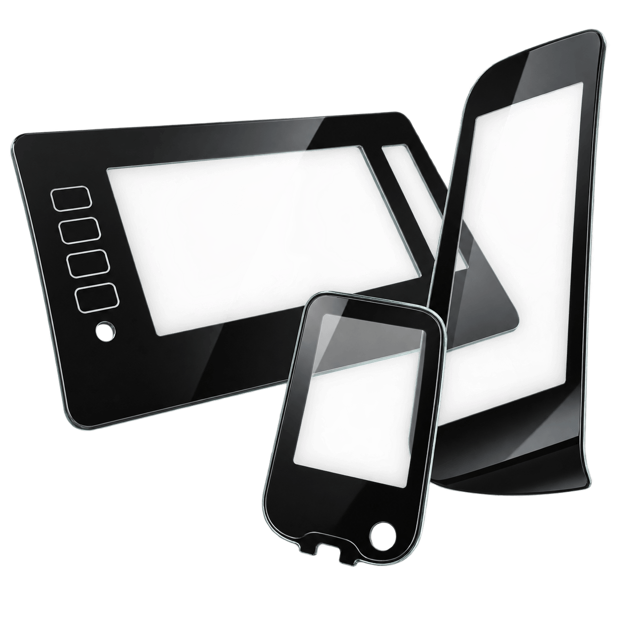
Custom Touch Panel Glass
Define the cover outline, thickness, finish and printing.
View solution →
Optical Bonding Display Solution
Review the interfaces between the cover, touch assembly and display.
View solution →Technical References
Abrisa Technologies: Dead Front Panels — specialist printed glass with controlled transmission.
Cat-i Glass: Surface Quality Criteria — printed-glass inspection, including transmission and backlit defects.
Teikoku: IRX-HF Glass Ink Technical Data — an example of wavelength-selective functional ink and transmission-control requirements; not identification of the ink used in our photographed sample.
The sample observations and sourcing-cost comments reflect DisplayMan’s project experience. External references explain related manufacturing principles; their numerical specifications are not adopted as DisplayMan product guarantees.
Project review
Discuss Your Custom Printed Cover Glass Project
Send your company details, front-view drawing, glass outline, border artwork, vector logo, window functions, surface-treatment requirements, sample quantity and expected production volume.