Display Tech & Engineering · Touch Integration
Choose Where Touch Is Integrated
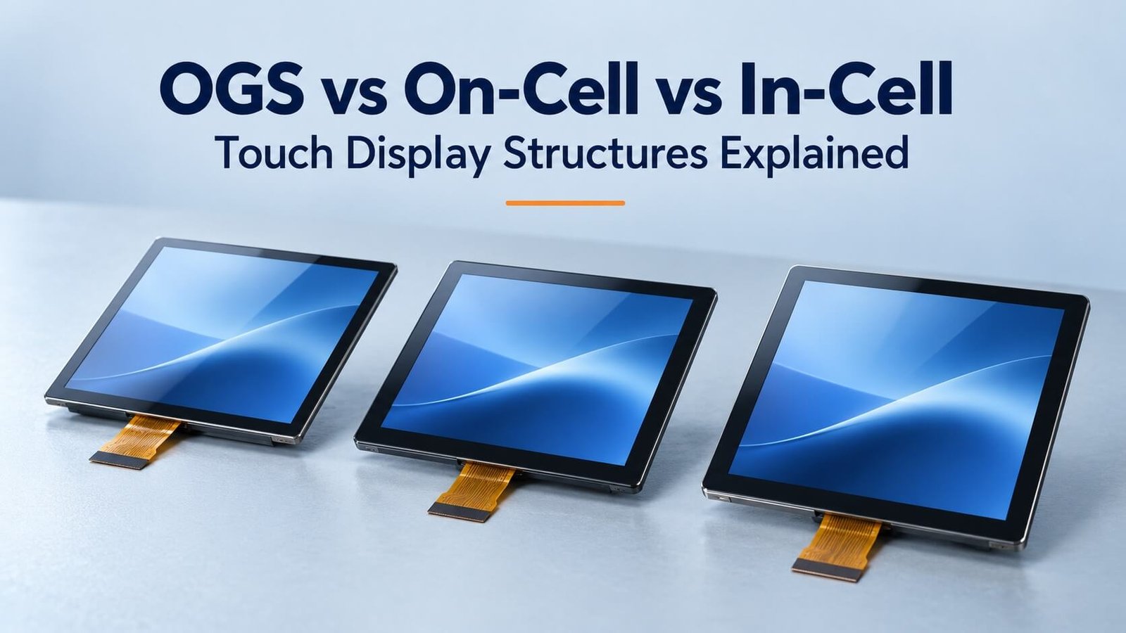
OGS integrates touch sensing into the cover lens, On-Cell places it on the display cell, and In-Cell integrates it within the display cell. These are sensor architectures—not three optical bonding methods.
For an OEM project, compare the available panel, cover design, controller, bonding process and sample tests together. DisplayMan helps review the complete touch display assembly rather than choosing an architecture by its name alone.
1. The Key Difference: Where Is the Touch Sensor?
OGS, On-Cell and In-Cell describe where touch-sensing electrodes are integrated. Optical bonding describes how optical surfaces are joined. These are related design decisions, but they are not interchangeable terms.
| Structure | Touch sensor location | What remains to be specified |
|---|---|---|
| Separate PCAP overlay, such as G+G or G+F+F | On separate sensor glass or film above the display | Cover construction, touch controller and bonding to the display |
| OGS: One Glass Solution | Patterned on the cover lens itself | Lens processing, controller and connection to the display |
| On-Cell | On an outer surface of the display cell; a typical LCD implementation uses the outer color-filter glass surface | Exact panel construction, cover lens, controller and bonding |
| In-Cell | Within the display cell, using dedicated or shared display electrodes | Panel architecture, driver integration, cover lens and host compatibility |
For OLED, there is no liquid-crystal cell. Touch electrodes can be integrated on the encapsulation structure, but the exact construction depends on the panel. Request the supplier’s cross-section rather than transferring an LCD layer diagram directly to OLED.
Layer Structure: OGS, In-Cell and On-Cell on LCD and AMOLED
Read each column from the viewing side toward the rear. These are simplified examples showing where the touch sensor belongs, not manufacturing drawings. Adhesive, electrodes and optical layers vary by panel.
| TFT LCD + OGS | TFT LCD + In-Cell | TFT LCD + On-Cell | AMOLED + On-Cell |
|---|---|---|---|
| 1. Cover lens with touch sensor patterned on its inner surface | 1. Protective cover lens | 1. Protective cover lens | 1. Protective cover lens |
| 2. Optical adhesive or designed air-gap assembly | 2. Optical adhesive / cover assembly | 2. Optical adhesive / cover assembly | 2. Optical adhesive / cover assembly |
| 3. Front polarizer | 3. Front polarizer | 3. Front polarizer | 3. Polarizer or other reflection-control structure, depending on panel |
| 4. Color-filter glass and color-filter layers | 4. Color-filter glass and color-filter layers | 4. Touch electrodes on the outer surface of the color-filter glass | 4. Touch electrodes integrated on the encapsulation structure |
| 5. Liquid-crystal layer | 5. Touch sensing within the LCD cell, using dedicated or shared electrodes Exact position and LC / TFT relationship depend on the design. | 5. Color-filter glass and color-filter layers | 5. OLED encapsulation / barrier structure |
| 6. TFT array glass | 6. Remaining LCD cell structure, including LC and TFT array glass | 6. Liquid-crystal layer and TFT array glass | 6. OLED emissive device layers and TFT backplane |
| 7. Rear polarizer | 7. Rear polarizer | 7. Rear polarizer | 7. Supporting substrate, glass or flexible material depending on panel |
| 8. LED backlight unit | 8. LED backlight unit | 8. LED backlight unit | No LCD backlight or liquid-crystal layer |
Important: OGS does not add a separate sensor glass beneath the cover lens. A typical LCD On-Cell sensor is outside the cell, whereas an In-Cell sensor is inside it. AMOLED On-Cell must be described using the selected OLED panel’s encapsulation design; it should not be drawn by copying an LCD color-filter stack. Hybrid structures and alternative optical stacks also exist.
2. OGS / Touch-on-Lens: Integrating Touch into the Cover
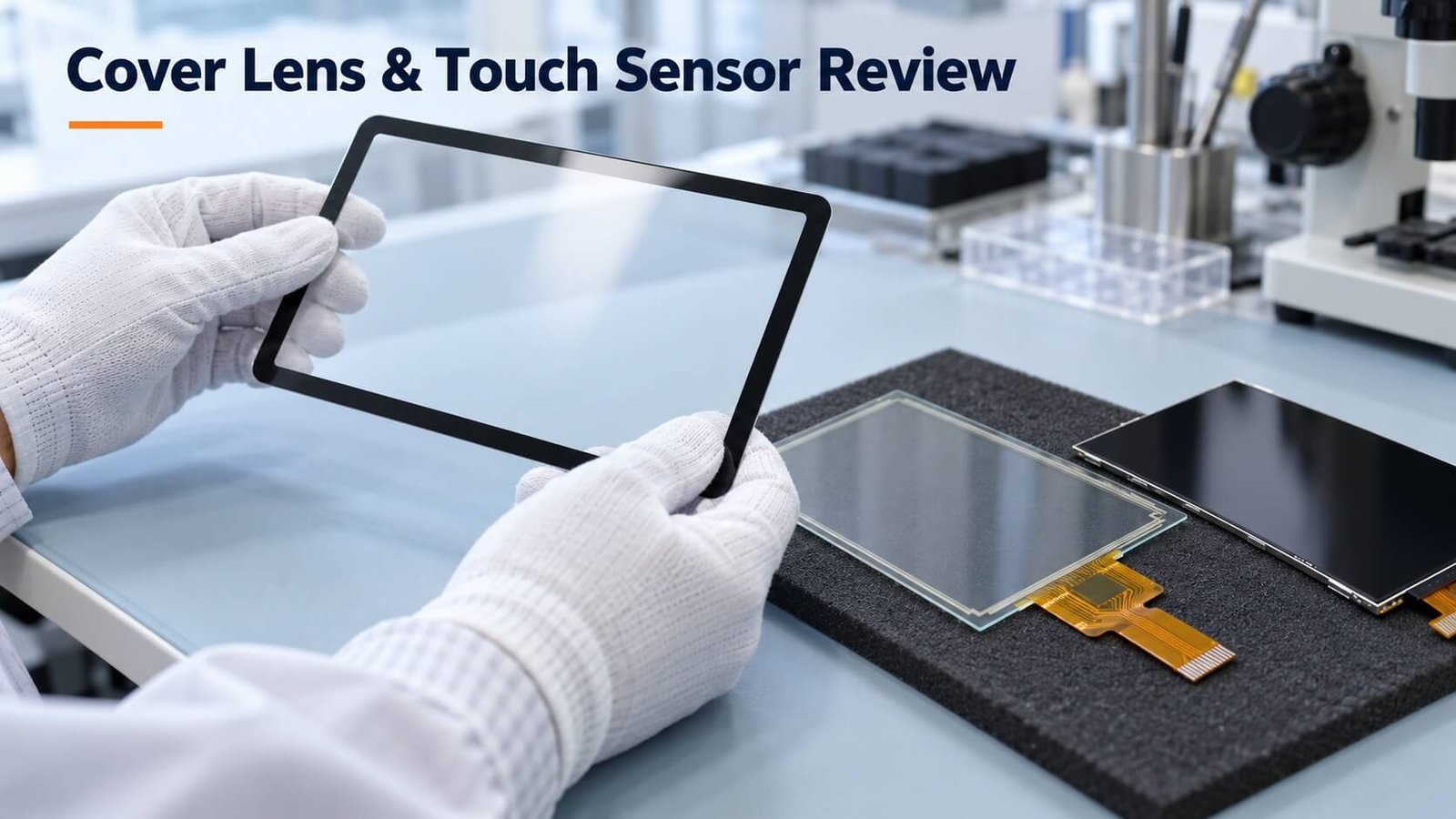
OGS combines the protective lens and touch-sensing substrate. Conductive electrodes and their interconnections are formed on the lens, removing the need for a separate sensor sheet in that particular construction. Touch-on-Lens (TOL) and Sensor-on-Lens are commonly used for closely related approaches; confirm what a supplier means by the term.
This can reduce layer count and the lens-to-sensor lamination operation compared with a separate cover-plus-sensor design. It does not remove every adhesive layer or guarantee lower finished-module cost.
Benefits worth evaluating
- Potential reduction in touch-overlay thickness and weight.
- Fewer optical interfaces than a comparable separate-sensor stack.
- Integration of sensing and lens appearance in one component.
Manufacturing trade-offs
Lens shape, edge quality, strengthening sequence, electrode patterning, decorative printing and electrical interconnection must work together. Cutting or edge damage after strengthening can affect glass strength; actual risks depend on whether the process works on a large sheet or individual finished lenses.
A change to the lens can also require a sensor redesign. Ask whether a proposed hole, curved outline, thick cover or printed border is compatible with the selected OGS process. For a custom industrial project, compare this with a conventional G+G or film-sensor overlay before choosing solely on thinness.
3. On-Cell: Touch on the Display Cell
On-Cell places touch-sensing electrodes on the outside of the display cell rather than on a separate overlay substrate. In a common TFT LCD implementation, they are formed on the outer surface of the color-filter glass, below the front polarizer.
In OLED constructions, integration can instead be associated with the encapsulation layers. OLED does not use an LCD backlight or a liquid-crystal layer. The panel drawing must identify the actual sensing position.
On-Cell can reduce the need for a separate touch sensor substrate. However, it still needs a suitable controller, electrical connection and cover assembly. The term does not specify USB support, glove performance, water behavior or the finished thickness.
What OEM teams should check
- Whether the exact display model is available with the integrated sensor.
- The supported controller and its firmware, interface and operating-system support.
- Display-noise coupling, synchronization and grounding requirements.
- Permitted cover lens thickness, bonding materials and mechanical changes.
- Replacement strategy when either display or touch fails.
Integrated touch is supplied as a panel-related platform. A cover-glass or touch-module supplier cannot simply turn any existing display into the same On-Cell design without the panel manufacturer’s involvement.
4. In-Cell: Touch within the Display Structure
In-Cell integrates touch sensing within the display cell. Depending on the design, sensing can use dedicated electrodes or share display electrodes through a coordinated drive scheme. Full In-Cell and hybrid structures differ; the label alone does not describe every electrode.
Reducing separate sensor layers can help produce a compact module. The commercial benefit depends on the available panel, controller integration, yield, quantity and assembly process. In-Cell is not limited to a prediction about a particular generation of smartphones: industrial display suppliers also offer integrated-touch options.
TDDI is a separate integration decision
TDDI means Touch and Display Driver Integration: touch control and display driving are combined within an IC. It describes electronic integration, whereas In-Cell describes sensor placement. Do not assume that every In-Cell module has an identical controller or interface arrangement.
Development and service implications
Touch and display functions are closely coupled. Approve the panel, controller firmware, host driver and mechanical assembly as a system. A custom cover may still be feasible within supported limits, but changing sensor geometry is generally a panel-platform decision.
If the integrated sensing function fails, repair may require replacement of the display module. Confirm the actual service unit rather than assuming that any integrated panel is disposable or that every separate overlay can be repaired economically.
5. Compare the Engineering Trade-Offs
There is no reliable universal star ranking for optical quality, sensitivity, impact strength or yield based only on these names.
| Decision | OGS | On-Cell | In-Cell |
|---|---|---|---|
| Primary integration | Sensor into cover lens | Sensor onto display cell | Sensor within display cell |
| Main design dependency | Lens and sensor manufacturing platform | Display panel and touch platform | Display panel, sensing and driver platform |
| Thickness opportunity | Removes separate sensor substrate in the overlay | Can remove separate overlay sensor substrate | Can remove separate overlay sensor substrate |
| Cover customization | Lens changes may affect sensing and production process | Separate cover options subject to platform limits | Separate cover options subject to platform limits |
| Electrical integration | Compatible external touch control required | Panel-compatible controller required | Coordinated sensing and display drive; TDDI possible |
| Cost comparison | Quote complete assembly and tooling | Quote available integrated panel plus assembly | Quote available integrated panel plus assembly |
| Key approval evidence | Lens strength, sensor function and bonding quality | Optical quality, noise performance and final touch tests | Optical quality, host compatibility and final touch tests |
The best option is the one that meets the product requirements with an available, supportable supply chain. A conventional separate PCAP overlay can remain a practical choice when cover customization, controller choice or sourcing flexibility matters more than minimum thickness.
6. Thickness: Keep the Original Example in Context
The following dimensions were recorded in the original article. They illustrate one set of cover-and-sensor constructions, not complete LCD or OLED module thicknesses and not current DisplayMan product specifications.
| Original example | Listed material stack | Recorded touch-stack total |
|---|---|---|
| G+G | 0.7 mm cover lens + 0.4 mm sensor glass | 1.25 mm |
| G+F | 0.7 mm cover lens + 0.188 mm ITO film | 1.05 mm |
| OGS | 0.7 mm cover lens with integrated sensing | 0.72 mm |
The totals exceed the simple substrate sums; the original source did not define every adhesive, coating or tolerance contribution. Do not use these figures as a manufacturing drawing. Request a stack-up specifying the lens, sensor, adhesive, polarizers, display and mounting allowance.
Do not infer drop strength or optical clarity from these totals. Glass composition, strengthening, edge processing, adhesive and enclosure support also matter.
7. Optical Bonding Still Needs Its Own Specification
An integrated sensor does not mean that the finished screen needs no bonding. A cover lens can still require lamination to the display with OCA or LOCA. Other constructions retain an air gap, subject to their mechanical and optical design.
Removing an air interface can reduce interface reflections and improve apparent contrast in ambient light. It does not increase the display’s native pixel contrast, eliminate every reflection or make a touchscreen waterproof.
Fewer layers can reduce some operations, but overall production yield is not automatically higher: more functions may be combined into one valuable component, changing the cost of a defect. Ask for a process-specific quotation and acceptance plan.
For adhesive layers, air gaps and assembly choices, see Optical Bonding vs Air Gap. For cover-surface reflection, glare and cleaning, see AR, AG and AF Cover Glass.
8. Select for the Application, Not the Label
| Project requirement | Useful starting point | What to confirm |
|---|---|---|
| Compact handheld device | Available integrated-touch display, or a thin overlay | Total stack, power, interface and volume |
| Industrial control panel | Compare integrated touch with separate PCAP | Gloves, electrical noise, cover and lifecycle |
| Custom outline or printed cover | Review overlay and OGS manufacturing options | Lens drawings, tooling and sensor constraints |
| Outdoor or bright ambient light | Evaluate the complete optical and thermal assembly | Reflection, readable contrast, brightness and temperature |
| Serviceable kiosk | Compare complete module replacement with separate assemblies | Access, bonding rework, spare parts and replacement cost |
DisplayMan can review the display, touch panel, cover and host requirements together. Architecture availability depends on the panel and supplier platform; custom OGS, On-Cell or In-Cell development is not assumed to be available for every size or quantity.
For sensor stacks, controller selection and tuning, use PCAP Touchscreen Customization & Tuning. For gestures and touch-input behavior, see PCAP Touch Interface Guide.
9. Sample Tests Before Approval
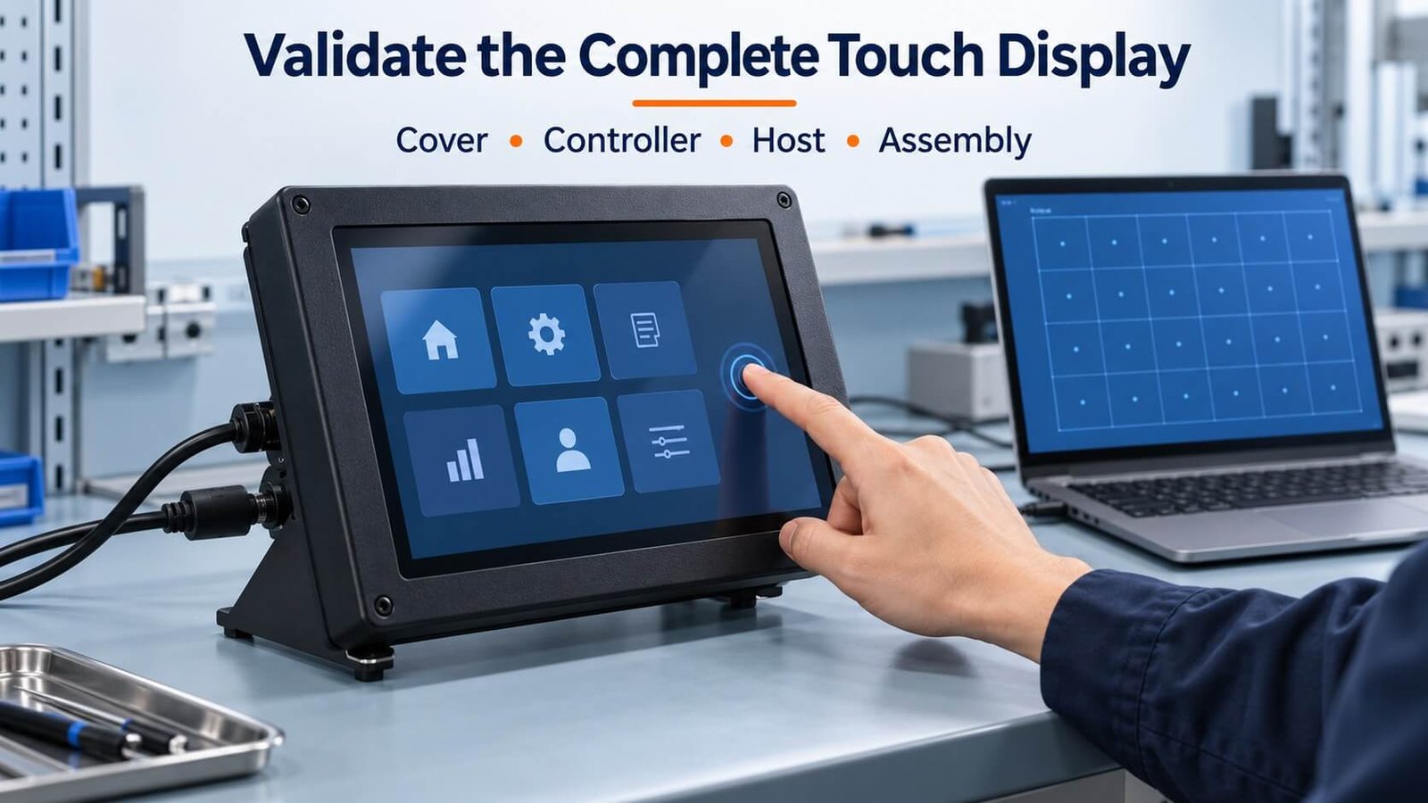
Test the final assembly, not only the bare panel. Include the cover, adhesive or gap, display driver, power supply, enclosure and intended host system.
- Optics: inspect brightness, reflection, haze, bubbles, visible electrode patterns and image uniformity at agreed conditions.
- Touch: test edges, corners, tracking, required touch points and unintended inputs using the real application.
- Special inputs: define glove material, thickness, water conditions and pen requirements where relevant; verify each supported case.
- Electrical conditions: test display patterns, backlight dimming, charging supplies, cables, grounding and relevant noise sources.
- Environment: agree temperature, humidity and durability tests appropriate to the product, with measurable acceptance criteria.
- Configuration: record panel and controller model, firmware, cover revision, bonding material and host driver versions.
A thin stack is not proof of reliable touch operation. Glove or water capability must be demonstrated on the agreed configuration rather than inferred from OGS, On-Cell or In-Cell terminology.
10. What to Send for an OEM Review
Send the display model or target size, resolution, active area, outline and thickness limit. Add the cover drawing, printed border, holes, surface treatments and bonding preference.
Provide the host platform, display interface, touch interface, power supply and cable arrangement. Specify the actual environment, required gloves or liquids, operating hours, estimated annual quantity, sample quantity and service-life expectations.
If a panel has already been selected, include its datasheet and available touch version. This helps establish whether to use an existing integrated-touch platform or a custom separate PCAP overlay before investing in tooling.
11. Frequently Asked Questions
Are OGS, On-Cell and In-Cell optical bonding methods?
No. They describe sensor integration. Optical bonding describes joining optical surfaces with an optically clear adhesive. Specify both decisions.
Is In-Cell always better than OGS or On-Cell?
No. It can offer a compact structure, but selection also depends on panel availability, touch performance, cover customization, support and total project cost.
Does On-Cell only apply to OLED?
No. On-Cell approaches exist for LCD and OLED. Their physical layers differ, so use the selected panel’s actual cross-section.
Does integrated touch remove the cover glass?
Not necessarily. A product can still need a protective cover and adhesive layers even when sensing is integrated into the display.
Can an existing LCD be converted into In-Cell?
Usually this requires a different panel design or an existing In-Cell panel platform. It is not achieved simply by changing the cover lens or adding a touch controller.
Is 100% light transmission a realistic general claim?
No. Real optical stacks have reflection and absorption losses. Compare measured values under a defined method rather than assigning universal transmission percentages to architecture names.
Explore Related Display Products
Choose a touch component, integrated display module or complete terminal according to your project scope.
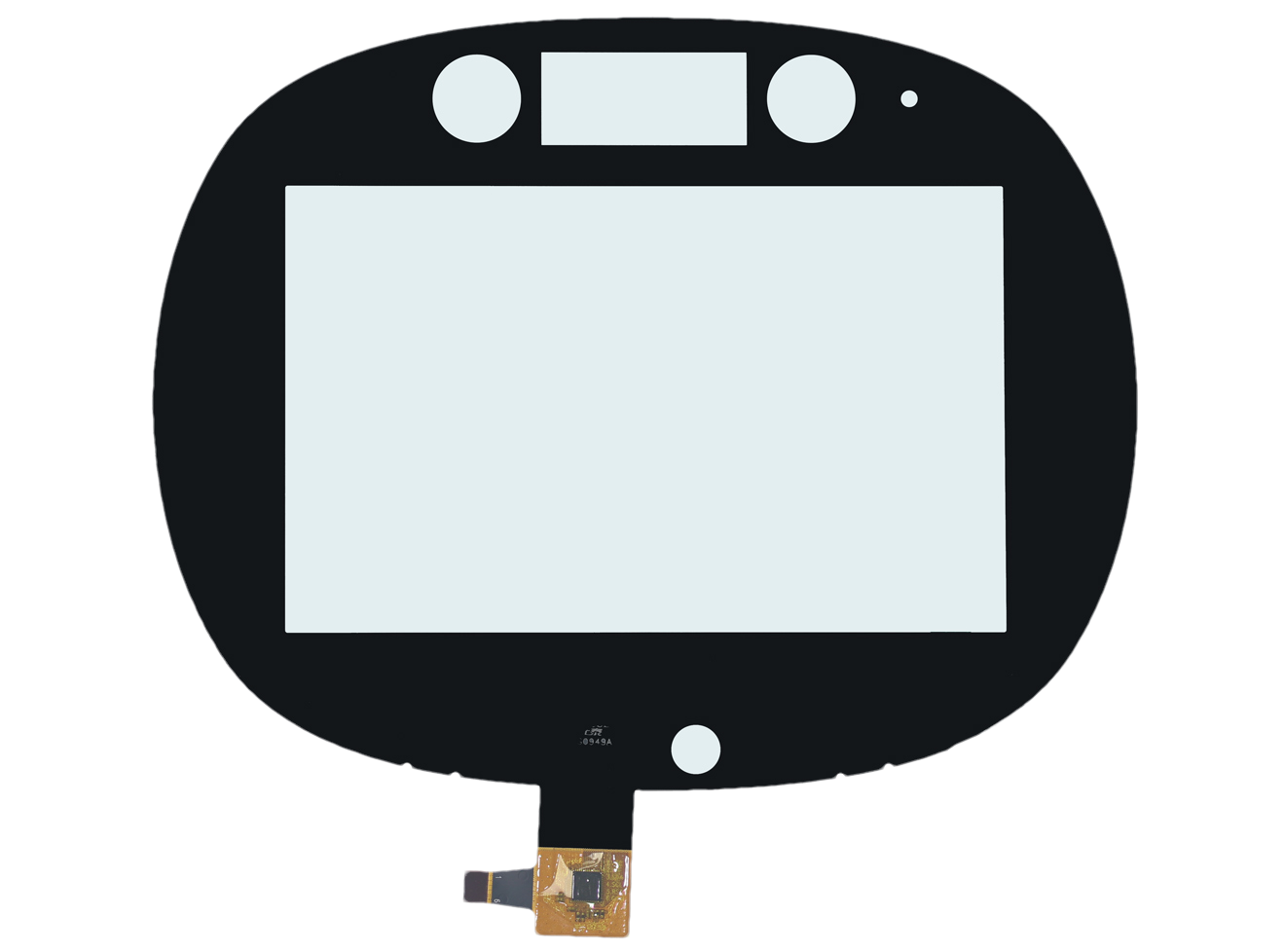
Capacitive Touch Panels
Review sensor construction, cover glass, controller and input requirements.
Explore product options →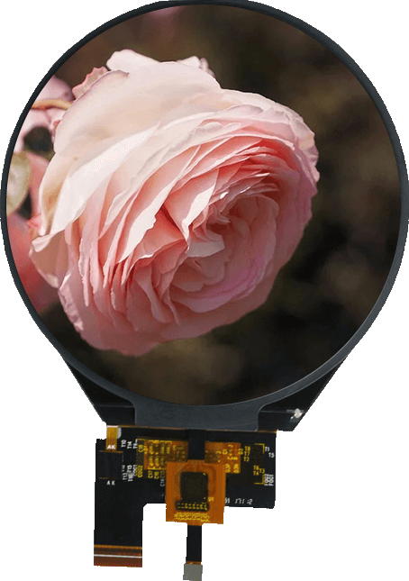
Touch Screen TFT LCD Displays
Select the display and touch assembly together around your host system.
Explore product options →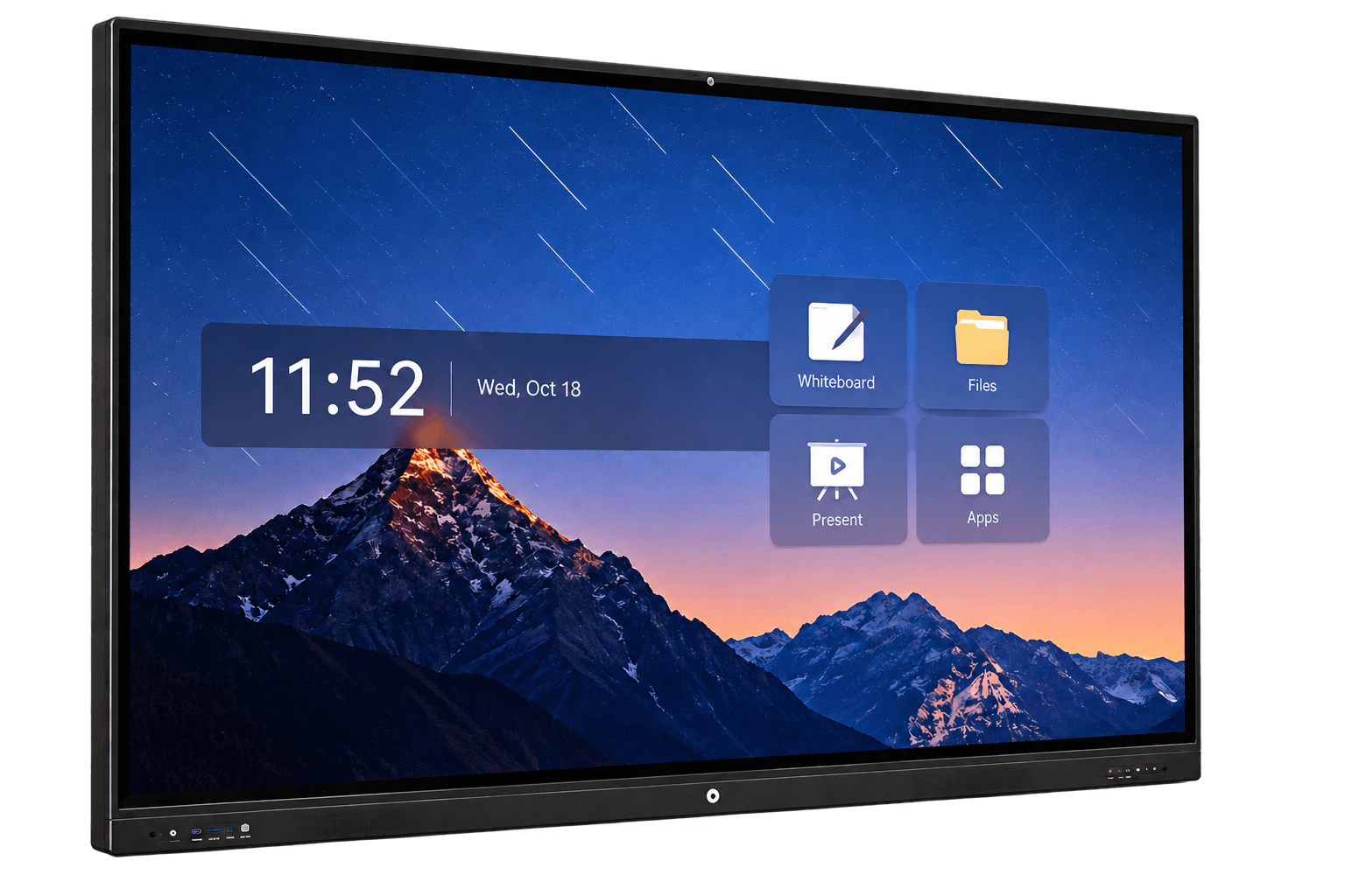
Interactive Flat Panels
Review complete large-format collaboration and terminal requirements; touch technology depends on configuration.
Explore product options →Project review
Review Your Touch Display Architecture
Send your display datasheet, cover drawing, thickness limit, host interface, operating conditions and quantity. DisplayMan can review a practical touch display integration direction.
Prefer to open the enquiry form here?
Technical References
Synaptics: touch and display integration white paper (2014–2015; used for architecture definitions, not current performance rankings).
Tianma: industrial displays and integrated touch options. Manufacturer platform information does not establish availability or performance for a specific DisplayMan configuration.