
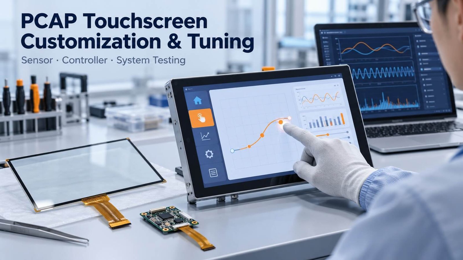
Display Tech & Engineering · PCAP Customization
Match the Sensor, Controller and Final Assembly
PCAP customization starts with the cover, sensor structure, controller and host interface. Tuning then balances touch detection and rejection of unwanted signals in the final product.
Specify the real display, glass, gloves, liquid conditions and electrical environment before approving a configuration. DisplayMan can review these requirements together as part of a custom touch panel or integrated display project.
1. What PCAP Customization and Tuning Actually Mean
Hardware customization defines the sensing system. Tuning adjusts how a particular controller measures and interprets that system. A successful touchscreen needs both to match the final product.
| Design level | Typical decisions | What must be confirmed |
|---|---|---|
| Mechanical and optical | Outline, cover glass, printing, sensor substrate and bonding | Drawing, viewing area, tolerances and assembly stack |
| Sensor and electronics | Electrode layout, routing, FPC, controller and power | Controller compatibility, electrical limits and host interface |
| Firmware and configuration | Thresholds, filtering, baseline tracking and supported operating modes | Available controller functions and an approved configuration revision |
| Application and host | Gesture interpretation, touch targets, orientation and recovery | Actual operating system, application and installation |
Do not treat tuning as a universal repair for a poorly matched sensor, excessive electrical noise or an unsupported cover thickness. Resolve the system design first, then qualify the configuration on representative hardware.
For single-touch, multi-touch and application gestures, use the separate PCAP touch interface guide. This article focuses on the engineering choices behind the interface.
2. How PCAP Detects a Touch
A PCAP sensor contains patterned conductive electrodes. The controller excites and measures these electrodes, looking for capacitance changes associated with a finger or another supported input. It does not simply count electrical charges deposited on the glass.
In self-capacitance sensing, a controller measures an electrode’s capacitance relative to its reference environment. In mutual-capacitance sensing, it measures coupling between transmit and receive electrodes. Some touchscreen controllers use both approaches to support different operating conditions.
The useful touch signal must be distinguished from display interference, power-supply noise, environmental changes and unintended contacts. Electrode geometry, cover thickness, grounding, the display stack and controller algorithms all affect this task.
Touch accuracy, report rate and complete-system latency are different specifications. A fast controller does not automatically produce a fast application if the host, software or filtering introduces delay.
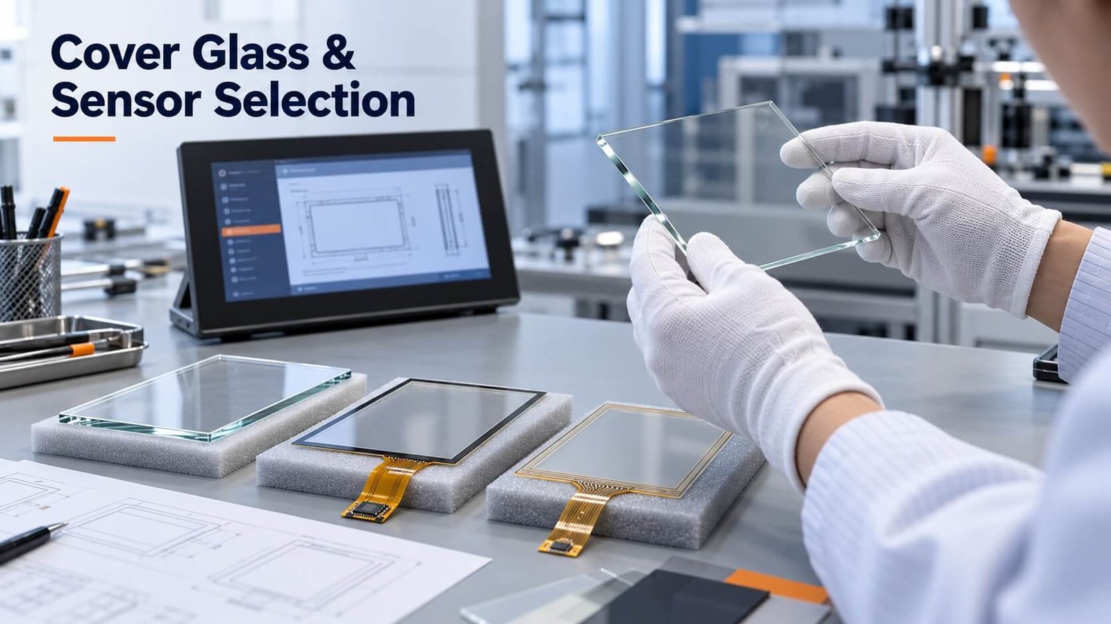
3. Choose the Stack-Up: G+G, G+F and G+F+F
Supplier abbreviations need a cross-section drawing. The first G commonly represents the cover glass, while later letters describe the sensor substrates; naming conventions are not identical across suppliers.
| Common description | Typical interpretation | Selection considerations |
|---|---|---|
| G+G | Cover glass plus a glass sensor substrate | Thickness, weight, optical quality, mechanical integration and controller match |
| G+F | Cover glass plus a film sensor substrate | Supported electrode implementation, routing, handling and optical requirements |
| G+F+F | Cover glass plus two film sensor layers | Lamination quality, alignment, optical behavior and electrical routing |
| OGS | Touch electrodes integrated onto the cover glass | Process compatibility, strengthening, printing, yield and replacement strategy |
A glass sensor can provide dimensional stability. Film can support a thinner or lighter construction in suitable designs. Neither description proves better impact resistance, accuracy or service life by itself. The cover, adhesive, mounting and complete construction determine the result.
Likewise, “two-layer film” and “two-layer glass” should not be interpreted as a mandatory film-and-glass combination. Ask what each layer does and how transmit and receive electrodes are implemented.
4. SITO, DITO and OGS Are Different Design Descriptions
SITO and DITO describe electrode implementations; OGS describes integration of the sensor with the cover glass. They are not three interchangeable grades of ITO material.
SITO commonly refers to single-layer ITO implementations. DITO often refers to double-sided ITO on a substrate, although supplier terminology varies. Confirm the actual layer and side arrangement rather than inferring construction from the acronym.
ITO is a transparent conductive material. A single conductive layer does not guarantee fewer false touches, while a dual-sided or multi-layer design does not make the cover glass twice as strong. Layout complexity, bridges or crossovers, controller channels, routing and manufacturing constraints affect the selected implementation.
OGS can remove a separate sensor substrate by integrating electrodes with the cover glass. This can reduce parts of the stack, but it also links decorative printing, sensor processing and cover-glass requirements more closely. Check custom-shape feasibility, replacement cost, sample availability and production yield before selecting it.
5. Electrode Patterns, Materials and FPC Routing
Electrode patterns are functional circuit geometry, not decorative artwork. Their pitch, shape, resistance, routing and overlap affect signal behavior and controller compatibility.
There is no universal rule that narrower lines always improve touch sensitivity. Resistance, parasitic capacitance, sensor dimensions, cover thickness and acquisition settings interact. A layout that works on one size or controller should not be scaled to a different product without review.
For some designs, suppliers may offer conductors other than ITO, including metal mesh. Evaluate the proposed material for visibility, optical artifacts, electrical resistance, manufacturing capability and the intended display resolution.
The FPC also matters. Confirm exit position, bend direction, connector pitch, contact side, pinout, stiffener and keep-out area. Avoid routing sensitive touch lines beside noisy power circuitry or assuming an arbitrary FPC extension is electrically harmless. Review FPC cable assembly when the cable is part of the custom integration.
6. Controller Location, Interfaces and Bonding
Chip mounting describes where and how the controller electronics are implemented. It is different from attaching the touch sensor to a display.
| Integration item | Typical implementation | Project review |
|---|---|---|
| Controller location | FPC-mounted electronics, a separate controller board or another supplier-specific package | Space, grounding, service access and routing |
| Host communication | USB, I²C or another supported interface | OS support, power, logic levels, pinout and firmware |
| Touch-to-display assembly | Perimeter attachment with an air gap, or qualified optical bonding | Optical performance, tolerance, rework and environmental reliability |
| Electrical bonding | Supplier-specific connections using processes such as ACF bonding | Pad design, process control and handling requirements |
An FPC is not itself a communication protocol. A USB controller and an I²C controller can require very different host integration even if both connect through a flexible cable.
Optical bonding may reduce internal reflections and change mechanical behavior, but it also changes the dielectric and electrical environment around the sensor. Approve touch performance after final bonding. See optical bonding vs air gap.
7. Cover Glass Thickness and Surface Treatments
A thicker cover generally makes the finger’s capacitive coupling to the electrodes more difficult to detect. The workable thickness depends on the controller, sensor layout, material, adhesive stack and required input conditions.
Do not approve thick-glass or glove operation using a bare sensor on the bench. Test the final cover and adhesive, including printed borders, mounting and the intended display. An unplanned air gap between the cover and sensor can change behavior substantially.
AR, AG and AF address different surface properties. They do not substitute for electrical tuning. Evaluate reflected light, haze, sparkle, cleaning and touch feel separately from the controller’s detection performance. For optical finish selection, read the AR, AG and AF cover glass guide.
Mechanical strengthening and environmental sealing are separate requirements. A functioning touch sensor does not prove that an enclosure has a particular impact or ingress-protection rating.
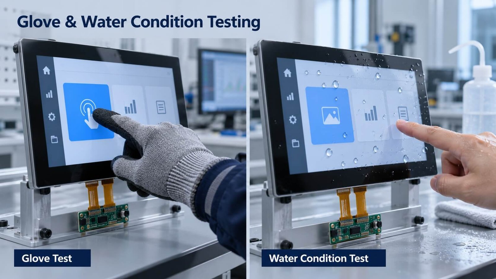
8. Tuning for Gloves, Water and Unintended Contacts
| Requirement | Define it clearly | Important trade-off |
|---|---|---|
| Glove operation | Actual glove material, thickness, fit, dry/wet state and required gestures | Detecting a weaker signal while rejecting noise and unintended contacts |
| Water rejection | Droplets, spray, flowing water, pooled liquid or another agreed condition | Avoiding false touches may require ignoring input during contamination |
| Wet-finger operation | Finger condition and the liquid present | Different from simply rejecting water-generated touches |
| Palm or large-contact handling | Which contacts should be ignored during which workflow | Supported controller functions and application behavior |
| Stylus operation | Passive capacitive or a supported active-pen system | A glove-capable controller does not automatically support every pen |
Increasing sensitivity can improve weak-touch detection while increasing unwanted detections. More filtering can stabilize reports while affecting responsiveness. The goal is an acceptable operating window for the defined workflow, not the highest possible sensitivity setting.
Water rejection does not necessarily mean normal touch operation under water. Define whether the system must reject false input, remain usable with a wet finger, or temporarily suppress touch and recover afterward. Test relevant cleaning liquids separately; they need not behave like clean water.
9. Noise, Grounding and the Final Display Assembly
A sensor that works beside a development laptop may fail after installation near a switching supply, backlight driver, motor or poorly routed cable. Test with the real display, power source, enclosure and grounding arrangement.
Compare operation with the display off and on, then vary displayed content and backlight settings. Record whether failures appear only while charging, switching a nearby load or touching a grounded metal frame. These comparisons help isolate the cause; they do not replace electrical investigation.
Depending on controller capabilities, engineers may adjust acquisition settings, frequency selection, thresholds or filters. Hardware work may include grounding, shielding, power integrity and cable routing. Qualification must follow the final design rather than an improvised bench connection.
Avoid exposing proprietary controller settings as generic recipes. A configuration value that helps one sensor can degrade another. Retain the exact controller model, firmware and configuration file with the approved sample.
10. PCAP vs Resistive Touch: Compare the Workflow
PCAP is a useful starting point for many glass-front interfaces and multi-touch applications. Resistive touch can remain practical where pressure input, a nonconductive tool or specific glove workflows are central requirements.
Neither technology is universally faster, more accurate or cheaper. Compare complete quoted assemblies, optical requirements, input methods, environmental conditions and host integration.
For a rugged industrial interface, the correct question is whether the proposed assembly meets the actual operating task. Do not reject resistive touch solely because a consumer smartphone uses PCAP, or assume every PCAP sensor can operate with heavy work gloves.
11. Sample Approval and Production Configuration Control
- Freeze the drawing, cover stack, sensor, controller, interface and host software used for evaluation.
- Test single contacts, required multi-touch gestures, corners, edges, dragging and repeated touches using the real application.
- Check the required gloves and liquid conditions, including recovery after removing contamination.
- Run with the final display, power supply and enclosure. Include relevant load changes and operating modes.
- Record false touches, missed touches, coordinate errors, report behavior and application-level response under agreed test conditions.
- Check startup, sleep/wake, disconnect/reconnect and recovery after an interrupted supply where relevant.
- Retain the approved firmware/configuration revision and a reference sample. Revalidate changes to the stack, electronics or installation.
A different LCD, power supply, cover-glass thickness or cable length can require renewed validation. Copying the old configuration into a changed assembly is not an approval process.
12. What to Send Before a PCAP Customization Quotation
- Display size and model, active area, resolution and intended orientation.
- Touch outline, viewing area, cover thickness, printing, holes and mechanical drawing.
- Proposed G+G, G+F+F, OGS or other stack, if already selected.
- Optical bonding or air-gap structure and enclosure mounting method.
- Host OS, interface, connector, supply and current controller if replacing a design.
- Required number of touches, gestures, gloves, stylus and liquid conditions.
- Operating environment, cleaning chemicals and nearby electrical equipment.
- Sample quantity, production forecast, project stage and acceptance criteria.
For an existing problem, also send a repeatable failure description and a short video showing the complete setup. A video of the symptom is more useful when accompanied by the exact panel, controller, firmware, power supply and connection details.
Custom sensor tooling, controller integration and firmware work have different development costs and quantity requirements. DisplayMan can review the actual scope before confirming feasibility, MOQ, sample plan and quotation. No universal glove thickness, cover thickness or waterproof claim should be assumed before review.
13. Frequently Asked Questions
Can every PCAP touchscreen be tuned for thick gloves?
No. The sensor, cover stack and controller must support the required signal conditions. Evaluate the actual glove and assembly before promising performance.
Does dual-layer ITO make a touchscreen more durable?
The electrode implementation alone does not establish impact or wear resistance. Review the cover glass, adhesives, mounting and complete stack against the required tests.
Can software fix all ghost touches?
No. Some issues involve grounding, noise, bonding, routing or incompatible hardware. Use repeatable tests to identify the cause before changing settings.
Are tuning and calibration the same?
Not necessarily. Tuning may alter detection and filtering behavior; calibration may refer to controller baselines or host coordinate mapping. Ask which operation is needed and what it changes.
Should I approve the touch panel before attaching the display?
A standalone test is useful for initial checks, but final approval should include the intended display, power supply, cover, enclosure and host application.
How is this different from the PCAP interface guide?
The interface guide explains interaction requirements and gestures. This guide covers stack selection, electrodes, electronics, tuning and sample approval.
Explore Related Display Products
Choose a touch component, integrated display module or complete terminal according to your project scope.
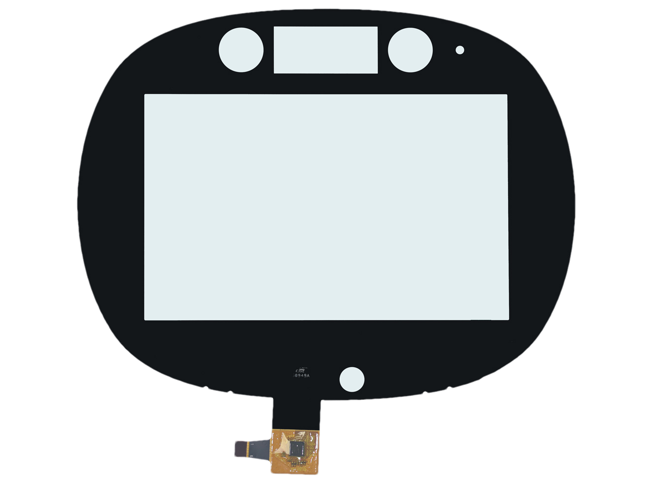
Capacitive Touch Panels
Review sensor construction, cover glass, controller and input requirements.
Explore product options →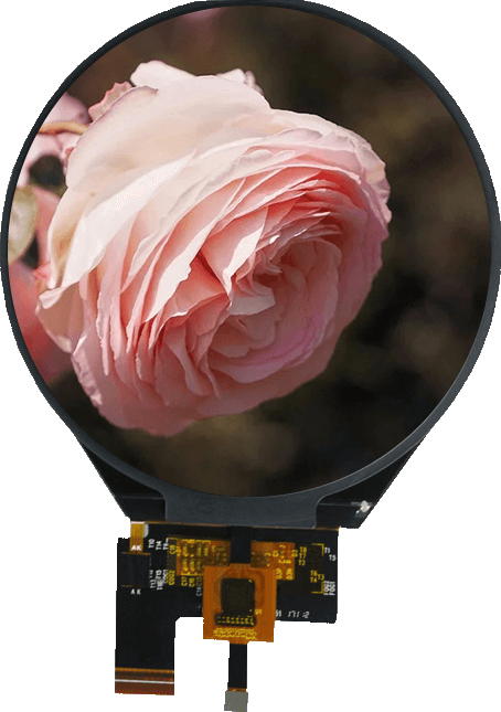
Touch Screen TFT LCD Displays
Select the display and touch assembly together around your host system.
Explore product options →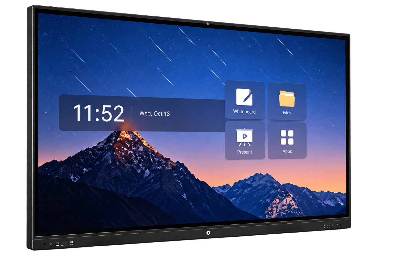
Interactive Flat Panels
Review complete large-format collaboration and terminal requirements; touch technology depends on configuration.
Explore product options →Project review
Review Your PCAP Customization Requirements
Send your display model, touch drawing, cover stack, host interface, required gloves or liquid conditions and production quantity. DisplayMan can review the hardware and tuning scope.
Prefer to open the enquiry form here?
Related Guides and Technical References
PCAP touch interfaces and gestures · Optical bonding vs air gap · AR, AG and AF cover glass
Microchip: maXTouch sensor design guide · Infineon: industrial capacitive touchscreen design
Controller documentation explains design principles and platform capabilities. Final specifications depend on the selected controller, sensor, assembly and agreed tests; these references do not imply that DisplayMan supplies every listed controller function.