Technology comparison · Greg’s project experience
Why Do We Use LED Backlights Today?
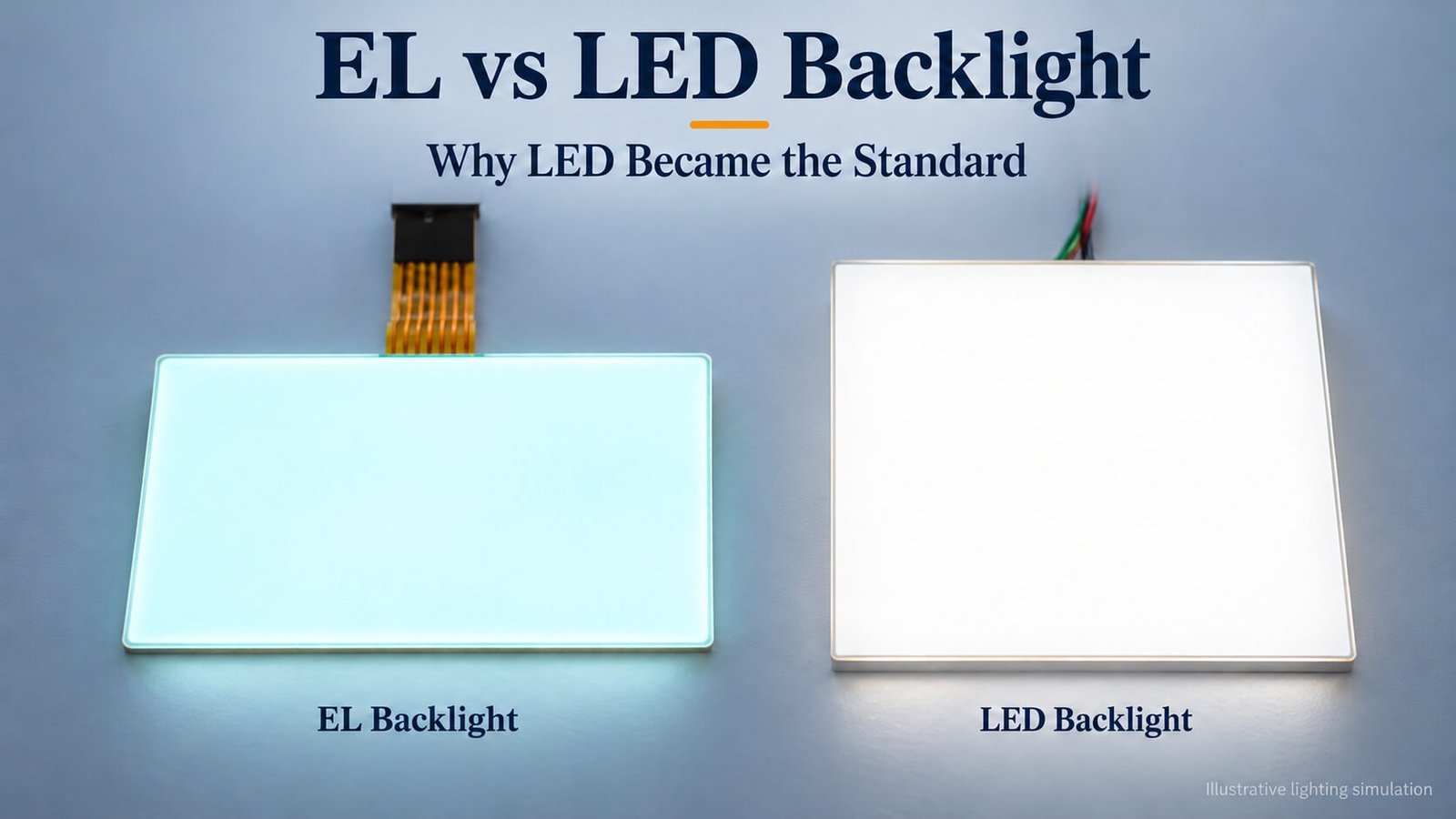
In the LCD projects I handle today, LED has become the standard backlight choice, and EL enquiries have almost disappeared. EL once offered an attractive thin lighting sheet. LED gives us a more practical range of brightness, color, drive and assembly options for new development.
This guide compares the two technologies and preserves my original backlight drawings, animations and ultra-thin LED project experience. The numerical examples describe particular designs, rather than universal specifications.
What Is an EL Backlight?
EL stands for electroluminescent. In the flat EL lamps discussed here, an alternating electric field excites a phosphor layer to produce light. The layered structure can provide thin, distributed illumination behind an LCD.
A suitable inverter converts the available supply into the AC drive required by the lamp. Brightness and aging depend on the lamp materials, drive voltage, frequency, temperature and moisture protection. The driver must match the lamp specification.
EL was attractive where a very thin lighting sheet and relatively uniform illumination were more important than high brightness. Its historical appeal helps explain why customers occasionally asked me about it even after LED had become our normal choice.
EL Backlight Features and Historical Technical Parameters
The following details preserve the technical background recorded in my original article. They are historical reference figures, not a current DisplayMan EL datasheet or operating instructions. The source lamp model, AC voltage convention and complete test method were not recorded, so a particular lamp’s specification must take precedence.
How Voltage, Frequency and Temperature Affect EL
EL is short for electroluminescent. The flat lamp has layered electrodes, dielectric material and phosphor rather than two literal paper plates. An alternating electric field excites the phosphor. Within the applicable lamp’s operating range, increasing AC voltage or frequency can increase brightness, but can also accelerate brightness decay.
My original discussion cited approximately 30–250 V and 50–2,000 Hz. It also recommended staying below about 140 V and 2,000 Hz in that context. These figures are retained as historical references; they are not general safe limits or recommended settings for an unidentified lamp. The original parameter list below contains a wider frequency range, which should not be combined with those recommendations into a single specification.
In that discussion, useful life meant the time for luminance to fall to 50% of its initial value. A theoretical figure above 10,000 hours was mentioned, while another example recorded about 8,000 hours at 100 V and 400 Hz. These different figures must be read with their operating conditions, not as equivalent guaranteed lifetimes. Temperature and humidity can strongly affect brightness decay and lamp life.
Original Features, with Their Applicable Limits
| Feature recorded in the original article | How to interpret it |
|---|---|
| Flat, solid-state area light source with broad-angle light output | Distributed illumination is an important EL characteristic. The finished LCD’s viewing angle is a separate property. |
| Very thin; a figure as low as 0.12 mm | A historical lamp construction example; confirm the finished thickness, including terminals and protection. |
| Lightweight | A useful characteristic of a thin sheet structure; compare complete assemblies. |
| Multiple luminous colors | Color depends on phosphors and any color-printing or filtering layers. |
| Flexible; a 5 cm bending radius was cited | Retain as an original example, not a universal bend limit. Confirm the lamp’s permitted radius and whether repeated flexing is allowed. |
| Resistance to shock and impact | A flat solid-state lamp avoids a fragile light-source tube, but electrodes, encapsulation and connections still need appropriate protection. |
| Low power consumption | Assess the illuminated area, brightness, drive and inverter losses together. |
| “Cold light” | Describes relatively low perceived surface heating in suitable use, not zero heat or a verified 97% electrical-to-light efficiency. |
| Long operating life | Specify the brightness-decay endpoint and operating conditions. The historical examples are listed below. |
| Custom shapes | Shapes can be designed into manufacturing; this does not mean a finished sealed lamp can be cut arbitrarily. |
| Low-UV illumination claim | A spectral measurement is needed for an application-specific claim; do not assume zero ultraviolet output. |
| Visibility in foggy conditions | Retained as an original application observation to evaluate, rather than a guaranteed advantage under every fog condition. |
| Soft, uniform illumination | A useful optical objective, without a medical guarantee that a light source can never cause discomfort. |
| Water-resistant or underwater applications | Require a lamp, encapsulation and electrical system specifically designed and rated for that use; EL itself does not guarantee waterproofing. |
| 30–250 V operating voltage; −35°C to +60°C temperature range | Original reference figures. The temperature range differs from the separate parameter list below and remains unverified. |
| Transformer- or IC-based drive circuitry | Use a matching inverter circuit that supplies the lamp’s specified AC waveform. |
Technical Figures Retained from the Original Article
| Parameter | Original recorded figure | Condition or qualification |
|---|---|---|
| Operating voltage | 30–220 V; 120 V described as optimum | Historical reference only. The original general discussion also cited 30–250 V; the AC measurement convention and lamp model were not recorded. |
| Operating frequency | 50–5,000 Hz; 1,500–2,000 Hz described as optimum | Not a universal optimum. The earlier discussion recommended no more than 2,000 Hz in its context. |
| Static capacitance | 6 nF/m at 20°C and RH <80% | The original unit and geometry basis need verification. Do not silently interpret this as a value per unit area. |
| Luminance | 30–126 cd/m² | Recorded at 120 V and 200–2,000 Hz; the precise relationship within the range was not supplied. |
| Power consumption | 108–1,032 mW/m | Recorded at 120 V and 200–2,000 Hz. The unit and geometry basis need verification; inverter inclusion was not stated. |
| Operating life | About 8,000 hours | Recorded at 100 V, 400 Hz and normal temperature/humidity. The original discussion defines life by a fall to half initial luminance; a complete test report was not supplied. |
| Continuous operating environment | −20°C to +70°C; RH <90% | Original parameter-list figure, distinct from the −35°C to +60°C range above. Do not combine the two into an extended rating. |
| Storage environment | −10°C to +40°C; RH <65% | Historical reference; verify packaging and storage conditions for the particular lamp. |
| Wire sizes listed | Ø0.9, Ø1.3, Ø2.3, Ø3.2, Ø4.3 and Ø5.0 | The original list did not establish units or whether these are conductor, insulation or another dimension. Retained for completeness, not cable selection. |
| Colors listed | Red, yellow, blue, green, orange, purple, pink and white | Available appearance depends on phosphors, printing and optical layers; these are not necessarily independently controllable colors. |
The value of retaining these details is to explain EL’s historical design trade-offs. They do not change my present project direction: LED is the normal backlight choice in the LCD enquiries I handle.
What Is an LED Backlight?
An LED backlight uses light-emitting diodes as the light source. In an edge-lit assembly, the LEDs inject light into a light guide plate, with optical films distributing it across the viewing area. In a direct-lit assembly, an LED array illuminates the area from behind through a suitable optical stack.
The backlight supplies light; the LCD controls its transmission to form the image. This distinction applies to both monochrome and color LCD projects. See our LCD basics guide for the complete display structure.
In the LCD projects I handle today, LED is the normal backlight choice. EL demand has almost disappeared from my enquiries. This article explains the technology comparison and my practical LED development experience, rather than suggesting EL as a normal starting point for a new project.
EL vs LED Backlight: The Main Differences
| Selection point | EL backlight | LED backlight |
|---|---|---|
| Light generation | Phosphor layer excited by AC drive | Semiconductor LEDs |
| Main historical strength | Thin light-emitting sheet with distributed illumination | Flexible brightness, color and assembly design |
| Thickness | Very thin lamp structures are possible | Complete thickness depends on LEDs, light guide or optical distance and films |
| Brightness | More constrained; increasing drive can accelerate aging | Scalable through LED selection, arrangement, current and thermal design |
| Drive | Lamp-specific AC inverter | Controlled LED current; supply depends on string arrangement |
| Color | Depends on phosphors and any printed color layers | Single-color, white or RGB LEDs, with optional printed optical layers |
| Lifetime comparison | Strongly dependent on operating conditions and brightness decay criterion | Dependent on LED quality, current, temperature and the complete assembly |
| Our present project use | Very rare in my current LCD enquiries | Our normal direction for new LCD backlight development |
These are design differences, not universal numerical specifications. For example, a lamp thickness does not include every connector, driver and mounting allowance in a complete product.
EL’s Historical Advantage: A Very Thin Lighting Sheet
Thinness was the reason I took EL seriously in the original article. Some EL sheets were described at around 0.12 mm, an attractive figure when customers were trying to minimize product thickness. Such a figure must be tied to a particular lamp construction rather than treated as the thickness of every EL assembly.
EL could also provide soft, distributed light without placing discrete LED packages along the illuminated edge. However, the complete product still needed its drive circuit, electrical connections and appropriate protection.
Low perceived heat at the luminous surface is not the same as zero electrical losses. Likewise, thin construction does not automatically establish waterproofing, unrestricted bendability or a particular operating-temperature range. These are product-specific requirements.
My Ultra-Thin LED Project: A 0.6 mm Light Guide Plate
One of the most useful examples from my own work was an LED backlight with a 0.6 mm light guide plate and approximately 0.9 mm total backlight thickness. Achieving that structure created real assembly challenges.

In that project, our conventional rigid-board LED mounting arrangement did not fit the thin optical structure, so we developed a dedicated FPC arrangement. The lesson was that an ultra-thin backlight is not simply a thinner sheet: the LED package, light-entry position, circuit carrier and mechanical stack have to work together.
Those dimensions describe that project. They are not a claim that 0.9 mm is the present minimum thickness for every LED backlight, or that every rigid PCB must have the same minimum thickness. The feasible structure depends on the viewing area, light source, brightness and assembly requirements.
For a new design, I start with the available space and optical target, then review the structure needed to achieve them. Our custom LED backlight quotation guide explains the information needed for that review.
Why LED Became Our Standard Backlight Direction
From my project perspective, LED gives us more useful engineering options: different light sources, edge or direct illumination, selectable colors, current control and a wide range of mechanical structures. Those options allow us to develop the backlight around the LCD and product enclosure.
Brightness is a major difference. With EL, increasing voltage or frequency can increase output but also changes aging and electrical demands. With LED, we can review the emitter type, quantity, arrangement and drive current alongside power and thermal limits.
Lifetime should not be reduced to a fixed “EL lasts this many hours, LED lasts that many hours” rule. Compare the stated brightness-decay endpoint and test conditions. LED life at the component level also does not guarantee the life of every connector, optical film or driver in a finished backlight.
For the projects I receive now, these practical advantages have made LED the routine choice. EL remains useful background knowledge for understanding earlier display designs.
How We Increase LED Backlight Brightness
Edge-Lit Backlight Design
In an edge-lit structure, we can review the number of illuminated edges, LED spacing and the light guide design. The original drawing below illustrates LEDs positioned along the light-entry edges.

In my earlier examples, LED pitch was often around 8–15 mm, with closer spacing considered where more output was needed. Those are examples of a design approach, not recommended pitch values for every size or LED package.
We also explored thicker light guides with additional LED rows, illustrated below. The original 3, 6 and 9 mm examples explain how the mechanical structure can change when more light sources are added.

Adding twice as many LEDs does not automatically deliver twice the useful front output. Optical coupling, drive current, heat and uniformity all affect the result. More LEDs and greater thickness can also increase cost, so we evaluate the actual brightness target before adding complexity.
Direct-Lit Backlight Design
A direct-lit array positions LEDs behind the illuminated area. LED spacing, optical distance and diffusion must work together to avoid visible bright points and uneven illumination.

The original drawing uses a 10 mm pitch example. In the earlier discussion I also considered wider and closer spacing to explain the trade-off between LED count and cost. Those examples were not completed-project specifications for every arrangement.
My original preference for edge lighting reflected the cost and structure of the small-module projects I handled then. It should not be read as a general recommendation against direct lighting. The right approach depends on size, brightness, available thickness, uniformity and production cost.
Color: Printed Optical Layers and RGB LEDs
Multiple visible colors can be produced in different ways. A printed color layer over a light source creates colors at fixed artwork positions. The original EL-related animation illustrates that visual approach.

It would be inaccurate to say all EL lamps emit only white light. Lamp color depends on the phosphor system and any filtering or printing used. The important point for the customer is whether the color is built into fixed artwork or can be changed electronically.
With RGB LED backlighting, we can mix the red, green and blue channels to obtain selectable colors. The animation below shows the principle of a color-changing backlight.

A color-changing backlight does not turn a monochrome LCD into a full-color pixel-addressable display. Whether the entire area or separate regions can change color depends on the optical layout and control design.
For a related practical example, our monochrome VA LCD guide shows how a deep black background and colored silk printing can create a richer fixed-segment interface.
Drive Circuits: Compare the Complete Electrical Arrangement
LEDs require appropriate current control. The forward voltage of one LED is not the same as the required supply voltage of a complete backlight. Series strings, parallel branches, resistors or current drivers determine the electrical arrangement.

The original drawing shows one example using three LEDs and a resistor in a branch associated with a 12 V supply. It explains one circuit arrangement; it is not a rule that every three-LED string needs exactly 12 V. LED characteristics, required current and control headroom must be considered.
A battery-powered product may also need an LED driver or voltage conversion, depending on its supply and LED string. It should not be assumed that a battery can directly and safely drive any backlight.
EL uses a different arrangement: a matching inverter generates AC for the lamp from the input supply. The original illustration below shows the additional drive hardware associated with that approach.

For either technology, confirm the complete electrical specification. This article intentionally avoids presenting the old voltage and frequency examples as universal operating recommendations.
What to Specify for a New LED Backlight
For a new LCD project, send the illuminated area, total outline, available thickness, target luminance, uniformity, color and available power. Include the intended LCD stack, connection position, operating environment and quantity.
State where luminance is measured: at the backlight surface or through the finished LCD. These values are not interchangeable because the LCD and other optical layers reduce transmitted light.
Use our LED backlight product page to review the product direction and the quotation requirements guide for a more detailed enquiry checklist. The technology comparison here explains why LED is our starting point; the project review determines the actual construction.
Frequently Asked Questions
Is EL still our normal recommendation for a new LCD project?
No. In my current enquiries, LED is the normal direction and EL demand is extremely rare. I retain this comparison to explain the technology and earlier design choices.
Why did EL attract attention historically?
Its thin light-emitting sheet and distributed illumination were attractive where mechanical thickness mattered more than high light output. The lamp still needed a suitable driver and integration structure.
Can LED backlighting also be very thin?
Yes. My original example used a 0.6 mm light guide plate with about 0.9 mm total backlight thickness and a dedicated FPC arrangement. Feasibility depends on the complete optical and mechanical requirements.
Does adding LEDs guarantee a proportional brightness increase?
No. More emitters can increase available light, but useful output also depends on current, optical coupling, temperature and uniformity. The complete assembly should be evaluated.
Does an RGB backlight make a monochrome LCD full color?
No. It can change the illumination color according to the backlight design. The monochrome LCD still has its defined segments or matrix structure; it does not gain independently selectable RGB subpixels.
From guide to product
Explore Related Display Products
Choose the product direction that matches the visible content, hidden assembly and integration needs.
LED Backlights
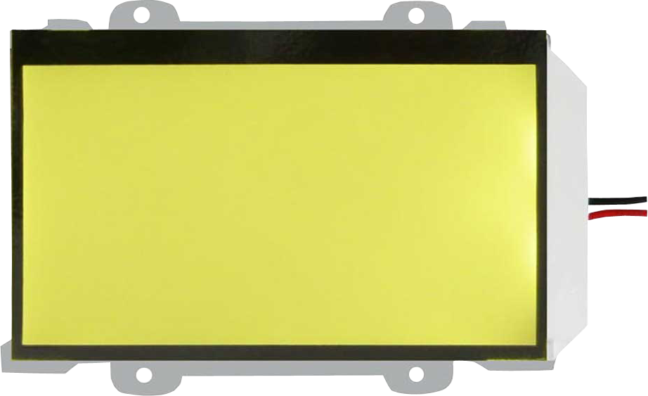
Review custom illumination, light guide, optical stack and electrical requirements.
Explore product options →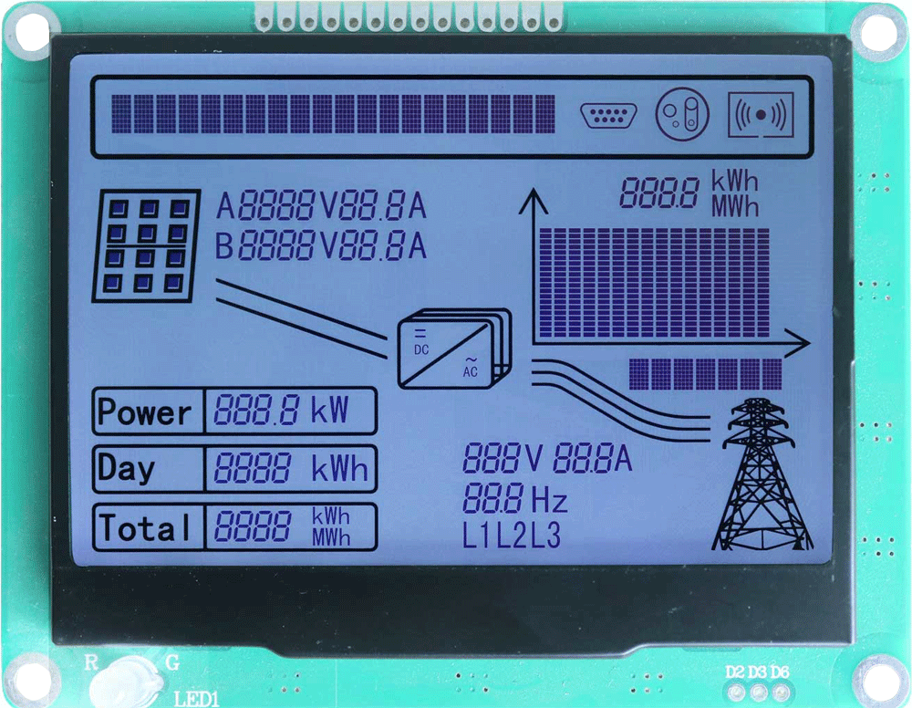
Monochrome LCD Displays
Match the backlight to a segment or dot-matrix LCD assembly.
Explore product options →
High Brightness TFT LCD Displays
Review color LCD requirements when ambient light demands more output.
Explore product options →Project review
Review Your LED Backlight Requirements
Send your illuminated area, available thickness, brightness, color, supply, environment and quantity. DisplayMan can review a practical LED backlight direction.
Prefer to open the enquiry form here?
References and Further Reading
Lumitek: electroluminescent lamps, colors and inverter arrangements · DisplayMan: custom LED backlight quotation requirements
The ultra-thin assembly dimensions and LED layout examples are retained from Greg’s original project discussion. Confirm present-day performance against the actual component and assembly specifications.