Dot Matrix
A pixel grid for changeable text, numbers, icons and simple graphics.

Bring illuminated text, numbers, symbols and simple graphics into compact products with a custom transparent LED display.
Choose a programmable dot-matrix layout, dedicated segments or a custom-shaped LED array. The outline, emission colors and FPC connection are developed around your application.
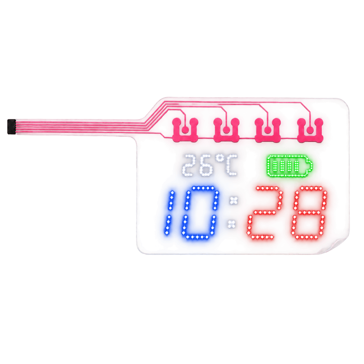
The display should fit your product: its visible window, enclosure curvature, connector position and available electronics space.
There is no fixed list of standard screen sizes in this family. A narrow format such as 60 × 15 mm can be a starting point for discussion. Circular, rectangular and irregular outlines can also be reviewed.
Final dimensions depend on the content, LED arrangement, circuit routing and assembly. We review the active display area separately from the overall outline, including the FPC tail and connection.
Individual LEDs generate the visible content. Clear areas between LEDs and circuit features allow the background to remain visible. The transparent film supports the circuit; it does not emit light by itself.
Passive perimeter features, conductive tracks and connection pads remain unlit. Only the specified LED elements emit light.
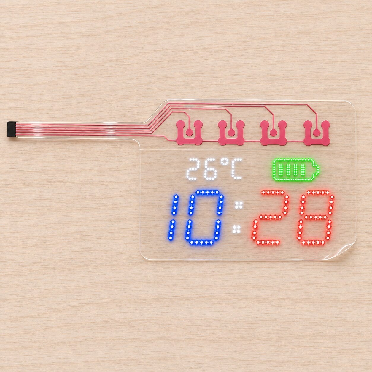
Illustrative custom layout showing discrete LED digits and symbols, passive upper routing and a transparent flexible carrier.
A pixel grid for changeable text, numbers, icons and simple graphics.
Predefined characters, logos and symbols for a focused product interface.
Application-specific shapes and lighting zones for device integration.
Product images are visual references for custom layouts and emission effects. Final appearance and specifications are confirmed with the approved sample.
Change the content within a defined pixel area.
A dot-matrix design arranges LEDs into rows and columns. Selected pixels illuminate to form text, numbers, symbols and simple graphics. It is suitable for changing messages, status information and basic animation, subject to pixel count and controller capability.
Layouts down to 0.5 mm can be reviewed. Around 1.0 mm is generally a better starting point when transparency is the priority. Closer spacing increases detail but also increases LED and circuit density.
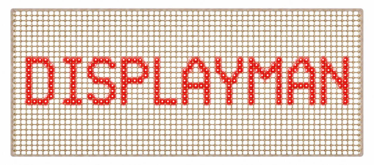
Visible LED points form changeable text on a transparent circuit. Red emission reference.
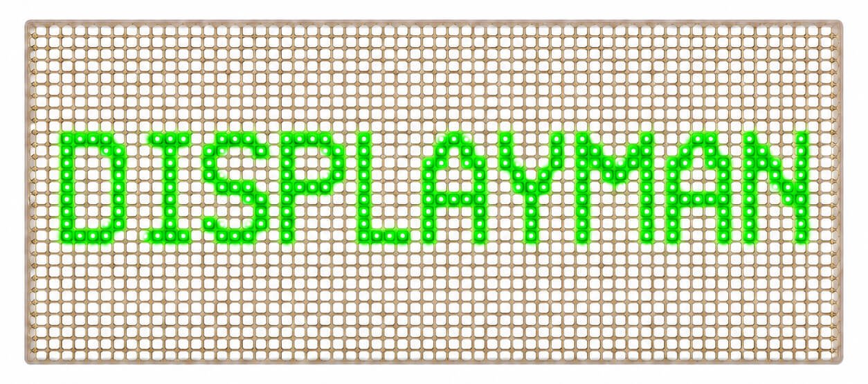
Visible LED points form changeable text on a transparent circuit. Green emission reference.
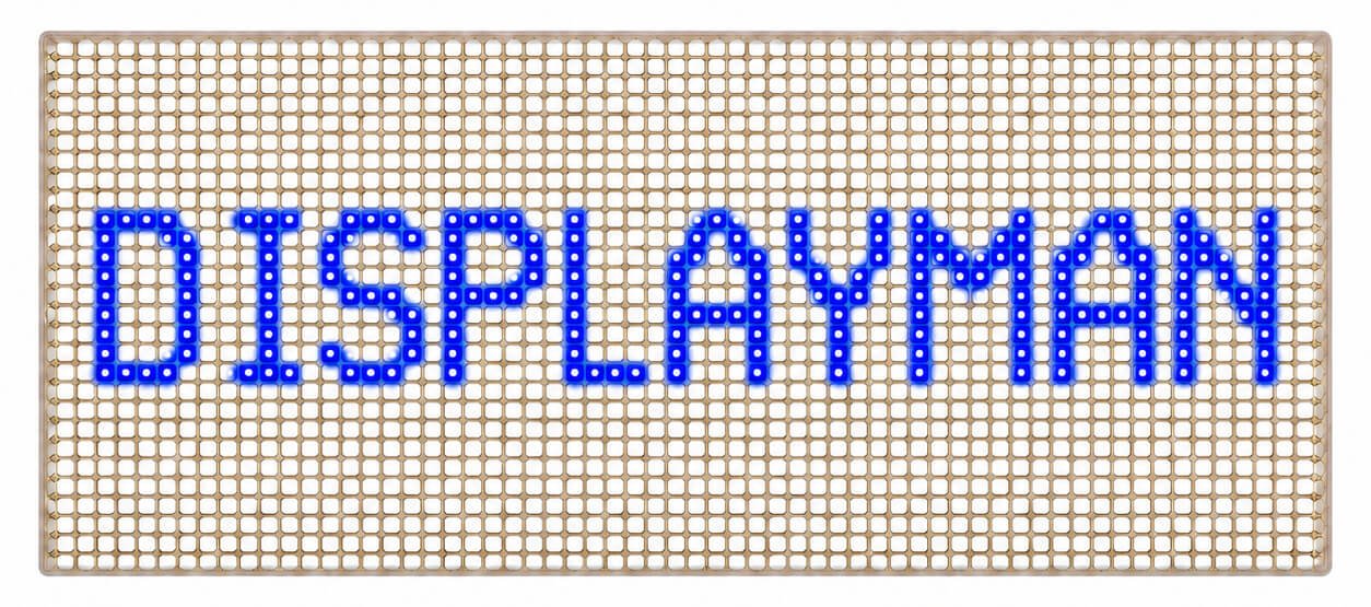
Visible LED points form changeable text on a transparent circuit. Blue emission reference.
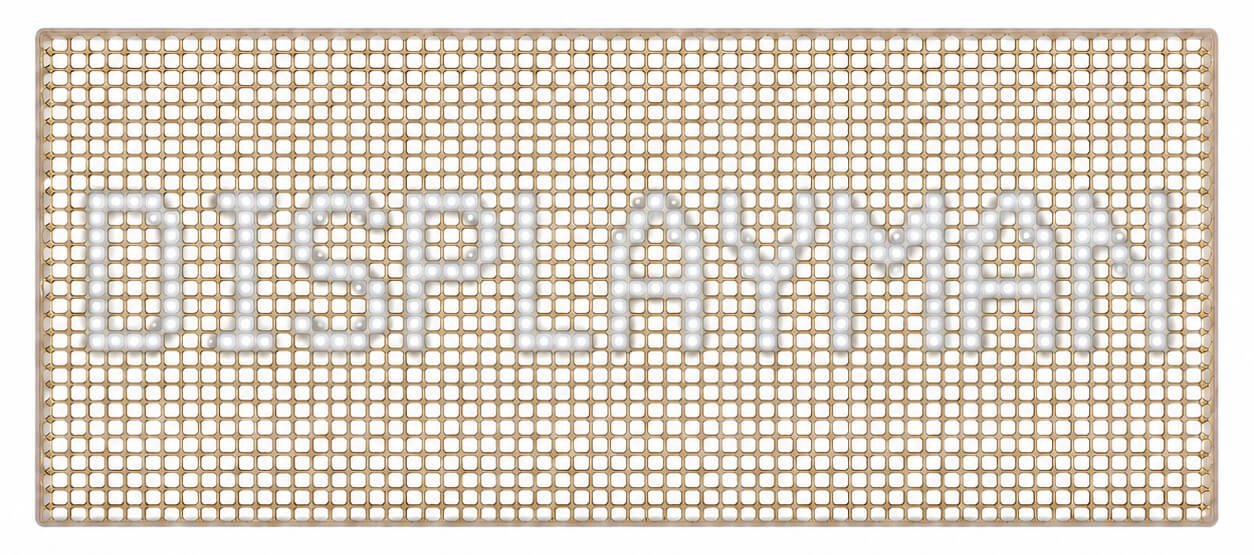
Visible LED points form changeable text on a transparent circuit. White emission reference.
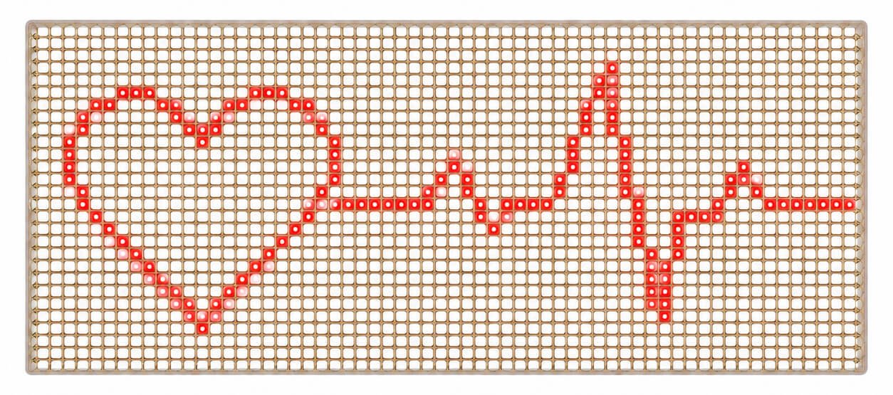
Visible LED points form simple graphics on a transparent circuit. Red emission reference.
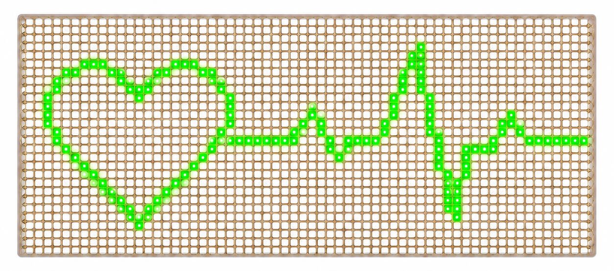
Visible LED points form simple graphics on a transparent circuit. Green emission reference.
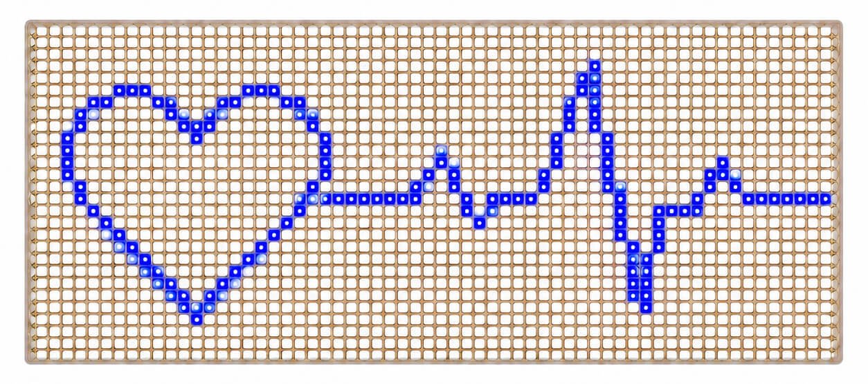
Visible LED points form simple graphics on a transparent circuit. Blue emission reference.
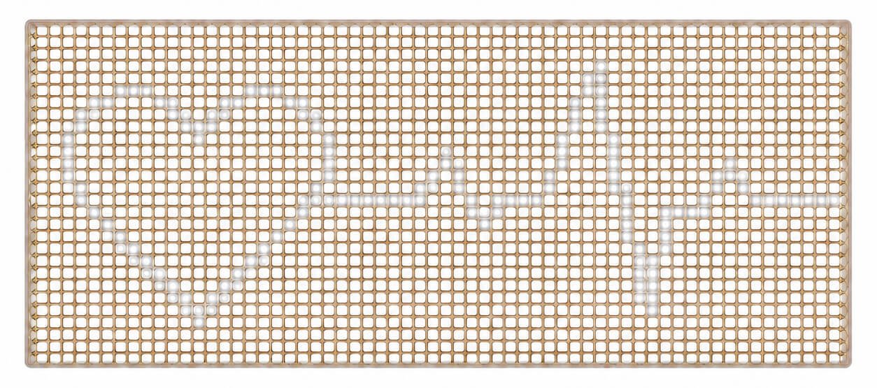
Visible LED points form simple graphics on a transparent circuit. White emission reference.
Dedicated numbers, symbols and brand elements in a layout designed for your interface.
A segment display uses predefined emitting elements. Segments can form time digits, temperature readings, battery indicators, mode symbols, warning icons or custom lettering. Each segment or group is assigned to the required control function.
In the circular examples below, only DISPLAYMAN, ON and the power symbol emit light. The outer ring and FPC routing remain unlit.
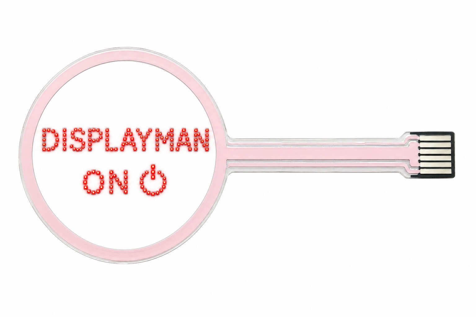
Individual LED beads form the lettering and power symbol. The passive ring and connection tracks do not emit light.
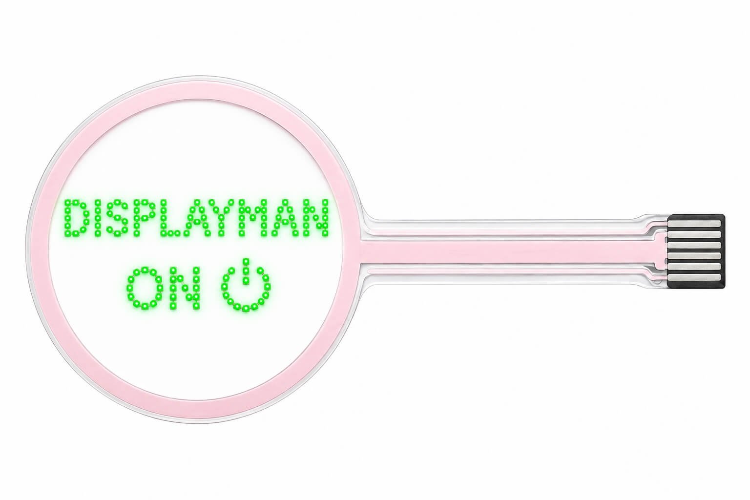
Individual LED beads form the lettering and power symbol. The passive ring and connection tracks do not emit light.
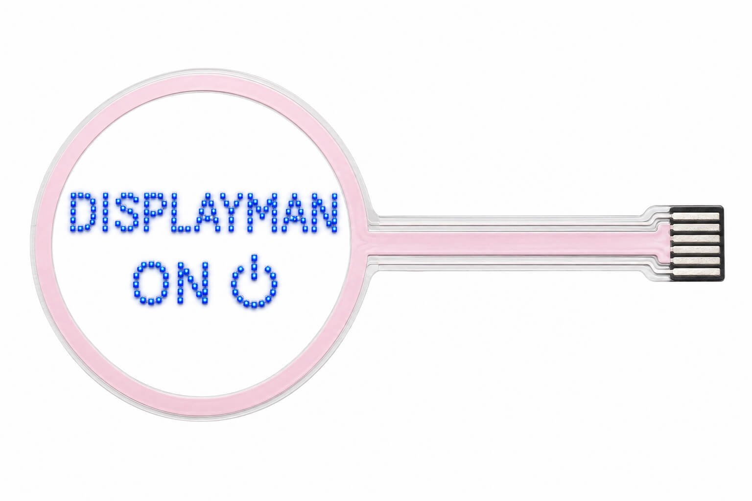
Individual LED beads form the lettering and power symbol. The passive ring and connection tracks do not emit light.
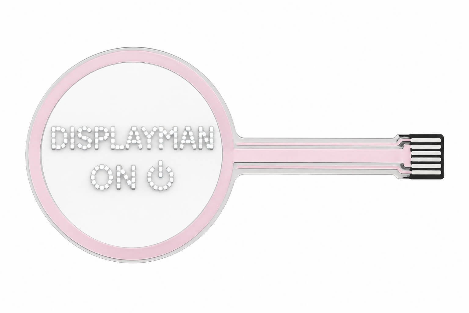
Individual LED beads form the lettering and power symbol. The passive ring and connection tracks do not emit light.
The controller changes which predefined elements are illuminated; the physical layout stays fixed. Confirm character shapes, symbol positions and independently controlled groups before finalizing the circuit. New symbols normally require a design revision.
| Configuration | Design Approach |
|---|---|
| Single Color | Red, green, blue or white emission for a consistent interface. |
| Different Colors by Zone | Assign colors to selected digits, symbols or functional areas. |
| RGB | Use suitable RGB LEDs and driving electronics for adjustable colors. |
| Dedicated White | Specify white LEDs when white emission is an important requirement. |
RGB color mixing and dedicated white LEDs are different configurations. Brightness adjustment, dimming and animation are reviewed with the selected LED packages and control system.
The transparent FPC material can have a highly clear appearance. Optical performance depends on the selected material and layer stack.
LEDs, tracks, pads, protection and bonding layers affect the finished display. Clear-film transmittance is not the same as whole-module transparency.
Evaluate the display against the intended background and ambient lighting, with its actual cover and enclosure.
LED spacing, trace routing and connector placement are reviewed together. Where practical, less-transparent connection and driver regions can sit outside the primary viewing window. Agree the measurement area and optical target for the actual assembly.
These displays use individual LED emitters. At close range, separate LEDs and their spacing remain visible. At around one meter or farther, suitably designed content can appear substantially smoother, depending on pitch, brightness and viewing conditions.
Transparent OLED uses an OLED pixel structure and emissive layers. Its close-up image appearance differs from the discrete LEDs used here. For handheld products, review samples at the intended operating distance.
Define the installed shape before finalizing the populated circuit.
Permitted bending depends on the substrate, conductive tracks, LED placement, solder joints, protective layers and connection structure. Review bend direction, radius, flat areas, tail routing and strain relief together.
Assembly bending and repeated flexing are different requirements. A flexible film does not automatically make the populated display suitable for repeated folding. Specify dynamic movement at the beginning of the project.
Adapt the LED outline and zones to the device structure.
Transparent flexible circuits can carry custom-shaped LED arrays for beauty-device integration. Openings, connection tails and emitting zones can be arranged around the mechanical design.
A display interface prioritizes readable information. A beauty-device array may instead prioritize LED positioning, emission distribution, zone control and thermal management.
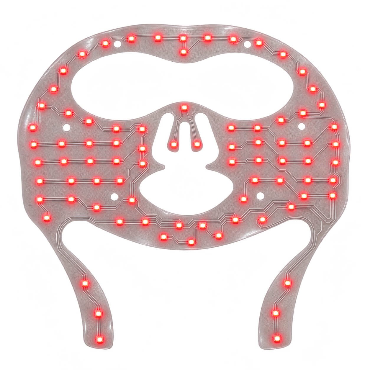
Custom-shaped transparent flexible LED array. Color-effect reference; wavelength and optical output are specified separately.
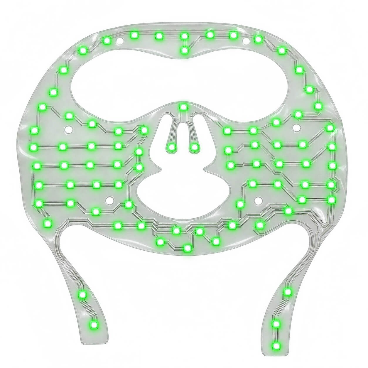
Custom-shaped transparent flexible LED array. Color-effect reference; wavelength and optical output are specified separately.
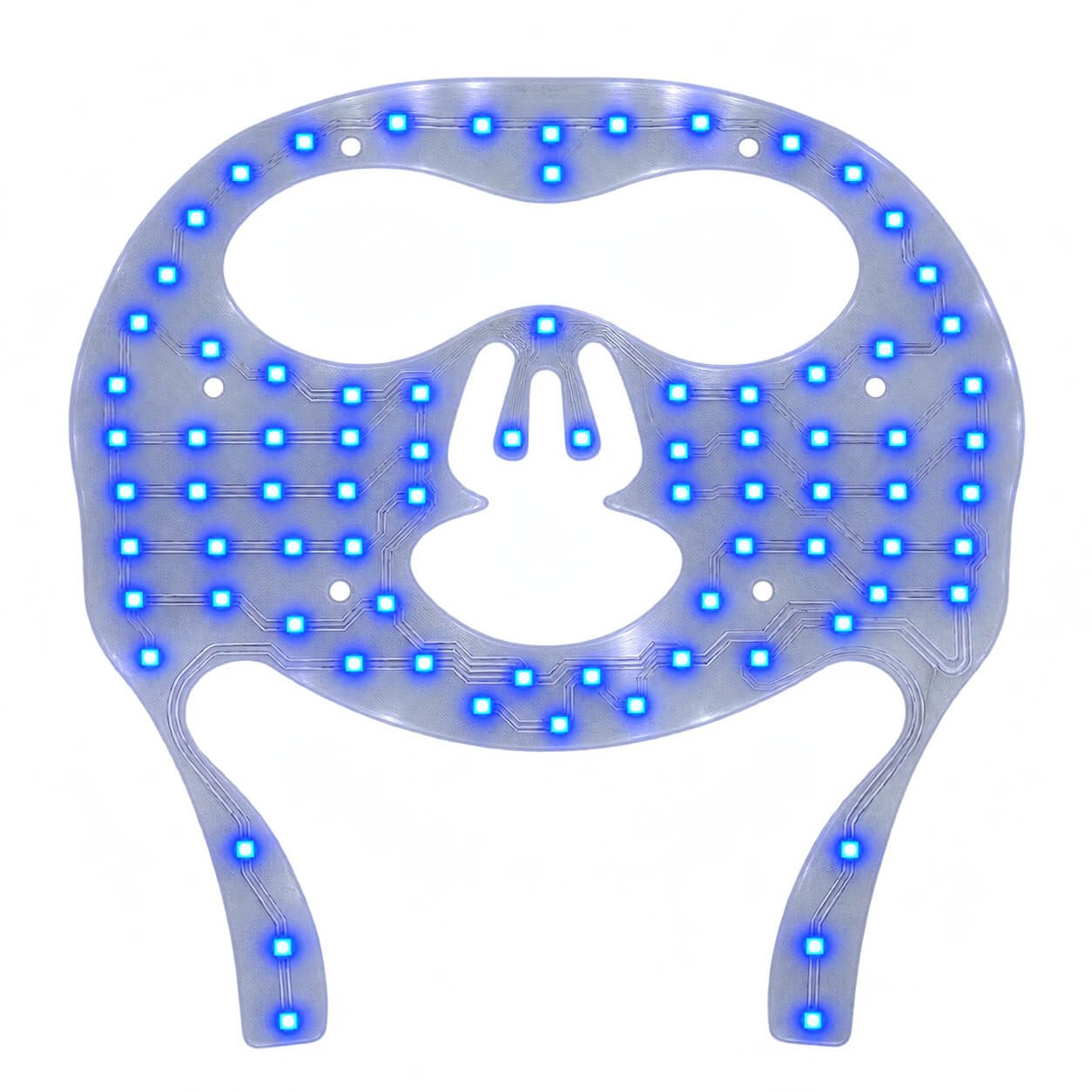
Custom-shaped transparent flexible LED array. Color-effect reference; wavelength and optical output are specified separately.
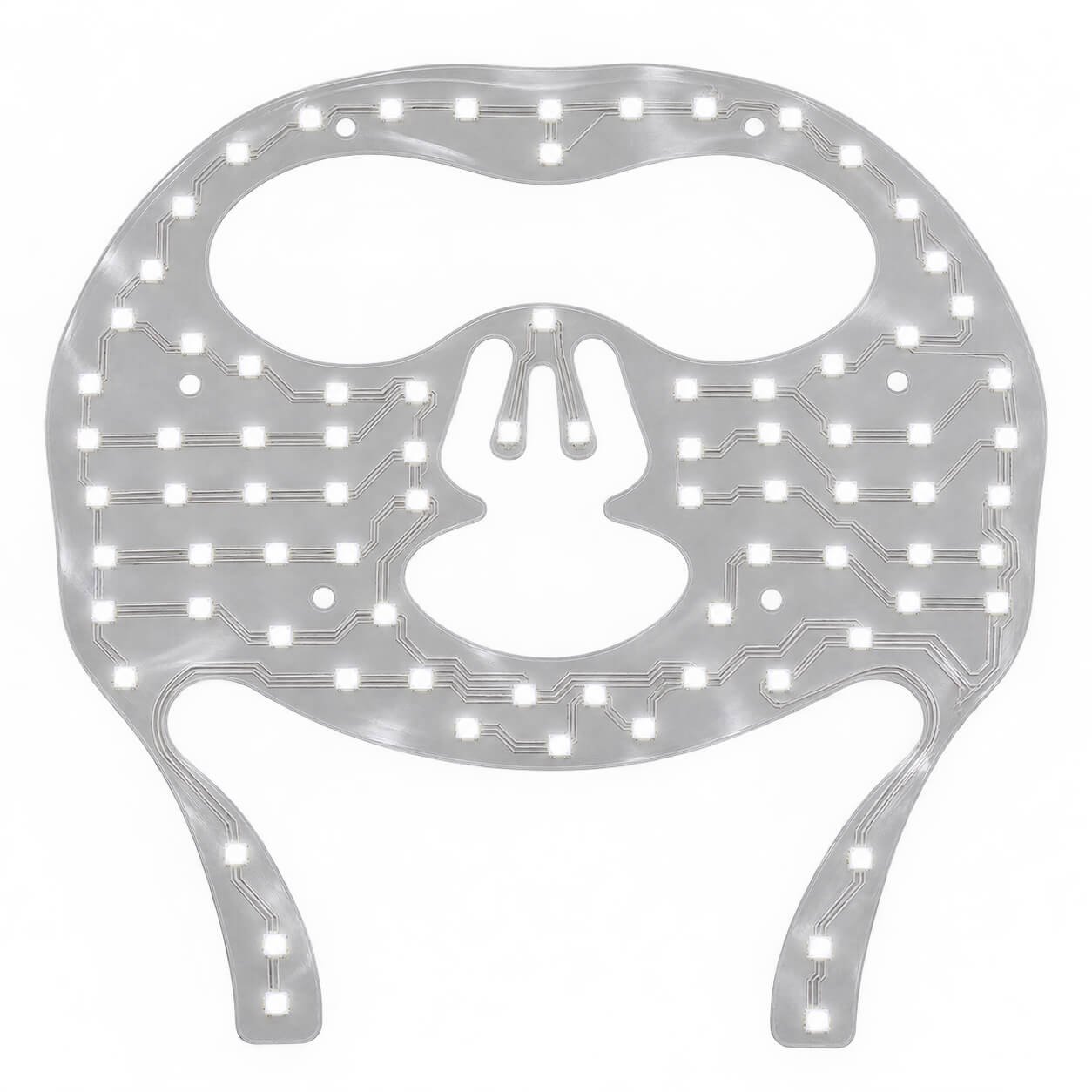
Custom-shaped transparent flexible LED array. Color-effect reference; wavelength and optical output are specified separately.
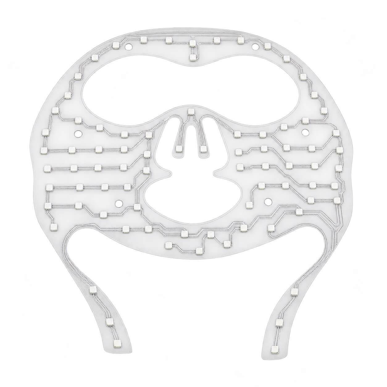
Unlit reference showing the film outline, LED positions and connection structure.
Provide the required outline, LED zones, wavelengths, optical output, uniformity, duty cycle, power and control method. Thermal behavior, encapsulation, cleaning and application-specific validation are reviewed separately. These images do not establish treatment performance.
| Item | What Can Be Reviewed |
|---|---|
| Overall Shape | Rectangular, circular, narrow strip or irregular outline. |
| Active Area | Dimensions and position of the emitting region. |
| Display Format | Dot matrix, dedicated segments or custom LED zones. |
| Pixel Pitch | Down to 0.5 mm for review; around 1.0 mm when transparency is prioritized. |
| Content | Text, digits, symbols, logos, simple graphics and lighting patterns. |
| Emission | Red, green, blue, white, RGB or different colors by zone. |
| FPC Connection | Tail length, exit direction, contact layout and connection position. |
| Control | Driver architecture, dimming, animation and host communication. |
| Mechanical Integration | Flat or approved curved mounting, protection and bonding. |
| Optical Targets | Brightness, viewing conditions and finished-module transparency. |
| Operating Conditions | Temperature, moisture, cleaning and protection requirements. |
| Commercial Requirements | Sample quantity, production volume, tooling and schedule. |
Final specifications are established for the approved design. There is no single universal brightness, thickness, voltage, maximum size or bending radius for every configuration.
Operating values, modes and status information within transparent product windows.
Custom display elements or shaped LED arrays integrated into the device.
Lightweight layouts for approved curves and unusual enclosure spaces.
Illuminated digits, symbols and brand elements in clear control panels.
Custom logos, short messages and decorative patterns.
Evaluation modules developed around the mechanical and electrical requirements of a new product.
| Your Requirement | Product Direction |
|---|---|
| Compact outline with dedicated digits and symbols | Custom transparent LED segment display |
| Changeable text or simple graphics | Custom transparent LED dot-matrix display |
| Application-specific lighting zones | Custom transparent flexible LED array |
| Large curved-glass or window advertising | Flexible Transparent LED Film Display → |
| OLED pixel-based transparent imagery | Transparent OLED Displays → |
| Premium transparent panel presentation | Transparent Micro LED Displays → |
Small-format modules are developed around an OEM product. Large-format transparent LED film systems are selected around installation area, module layout, viewing distance and content playback.
Describe the product, installation, viewing distance and operating environment.
Provide text, symbols or graphics. Identify independently controlled elements for segment designs.
Confirm the display window, total outline, FPC tail, connector and curvature.
Define color, brightness targets, power, control behavior and operating conditions.
Approve the drawing, then evaluate samples in the intended enclosure.
Agree appearance, functions, assembly requirements and inspection criteria.
Overall dimensions, active area, drawing or sketch, openings, mounting, curvature and FPC exit.
Exact content, format, colors, viewing distance, ambient lighting, power and host-controller requirements.
Prototype quantity, production forecast, target schedule, destination market and required compliance conditions.
This family is fully custom. The outline, active area, LED layout and FPC connection are developed around the application rather than selected from a fixed size list.
A format around 60 × 15 mm can be reviewed. Feasibility depends on the content, LED package, pitch, routing and connection requirements.
The practical size is confirmed through engineering review. Send the required outline and active area. A fixed maximum is not specified for this custom family.
Dot matrix uses a pixel grid for changeable content. A segment display uses predefined emitting elements for specific characters, symbols or logos. Its physical layout stays fixed.
Custom dot-matrix layouts down to 0.5 mm can be reviewed. Around 1.0 mm is generally a better starting point when transparency is the main priority.
Clear substrate transmittance and completed-display transparency are different measurements. LEDs, tracks, protection and the final assembly affect the result. Agree the requirement for the actual module and measurement area.
No. Passive rings, conductive tracks and connection pads do not emit light. Only the specified LEDs illuminate. An illuminated ring would require a separate LED layout.
Yes. At close range, individual emitters and gaps are visible. Content appears smoother as viewing distance increases, depending on pitch, brightness and viewing conditions.
Designs can use individual red, green, blue or white emission, different colors by zone, or RGB operation. Dedicated white LEDs and RGB color mixing require different configuration decisions.
Dot-matrix designs can support changing graphics or animation when pixel count and controller capability allow it. Video suitability depends on resolution and refresh performance. Segment displays illuminate predefined content.
Approved bending may be possible within the assembled display’s mechanical limits. Repeated folding is a separate requirement and must be evaluated during development.
Custom-shaped LED arrays can be reviewed for beauty-device integration. Define the outline, wavelength, optical output, control, thermal behavior and validation requirements.
The bare display requires suitable driving electronics. HDMI input, USB communication or another interface is a controller-level requirement to specify during development.
These depend on the custom design, electronics, sample requirements and production quantity. A project-specific quotation follows review of the application and drawing.
Share your outline drawing, display content and expected quantity. DisplayMan will review the dot-matrix, segment or custom-array approach, together with the emission colors, transparent circuit layout, FPC connection and integration requirements.
For an engineering review, please include your outline dimensions, display artwork, emission colors, FPC requirements, quantity and project schedule.