Greg’s monochrome LCD engineering experience
What Do ITO Glass and Polarizers Do in an LCD?
Patterned ITO electrodes apply the drive field, liquid crystal changes the optical behavior, and polarizers help convert that change into visible contrast. Their design also affects thickness, viewing appearance, processing and cost.
This DisplayMan guide preserves my original eight illustrations and practical examples, including mother-glass layout calculations, SEG/COM connections, sample tooling and colored silk printing.
How ITO Glass, Liquid Crystal and Polarizers Work Together
A conventional monochrome LCD cell contains two glass substrates with patterned transparent electrodes, alignment layers, a controlled cell gap, liquid crystal and a perimeter seal. Polarizers and any reflector or other optical layers form the required optical stack.

The original description compared the cell to a sandwich, which remains a useful starting point. In a traditional filling process, the sealed cell has a fill opening through which liquid crystal enters, and the opening is subsequently sealed. The gap is only a few micrometers in the original discussion; the actual design determines its value and process.
The liquid crystal does not emit the image light. An electric field changes its optical behavior, and the complete optical stack converts that change into visible contrast. Reflective designs use ambient light; transmissive designs use a suitable backlight. See our LCD basics guide for the broader principle.
What Is ITO Glass?
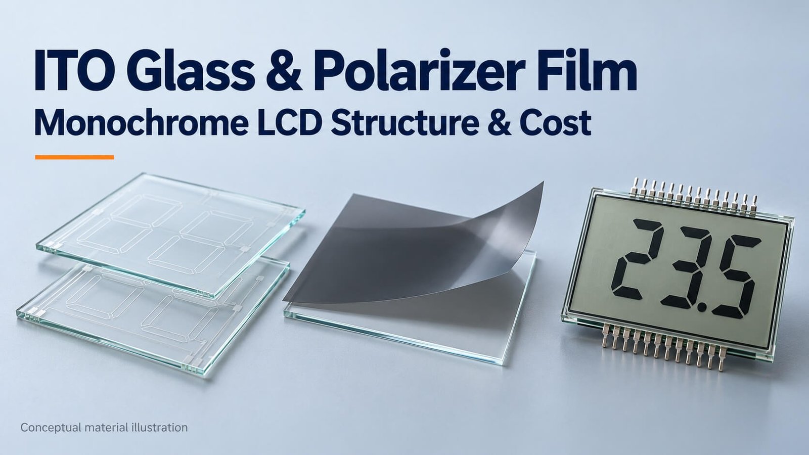
ITO means indium tin oxide. ITO glass is glass carrying a transparent conductive coating. In a custom monochrome LCD, the coating is patterned into the electrodes and routing needed to control the segments or matrix.
Transparency and conductivity have to be considered together. Sheet resistance, optical transmission, coating uniformity, defects and the glass surface can affect the design. “Transparent” does not mean lossless, and “conductive” does not mean it has no electrical resistance.
The electrodes carry the drive signal; they are not visible metal wires placed across the viewing area. The cell still requires the right alignment, liquid crystal material, gap, drive waveform and optical layers to produce a usable display.
Glass Thickness and the Complete LCD Thickness
My original article listed four glass thicknesses commonly encountered in our monochrome projects: 0.4, 0.55, 0.7 and 1.1 mm. These are the choices discussed in those projects, not the only ITO glass thicknesses available in the entire industry.
| Each glass substrate: original example | Complete LCD panel thickness recorded | Historical relative cost |
|---|---|---|
| 0.4 mm | Approximately 1.4 mm | Higher |
| 0.55 mm | Approximately 1.7 mm | High |
| 0.7 mm | Approximately 2.0 mm | Medium |
| 1.1 mm | Approximately 2.8 mm | Lower |
The complete figures include more than the two bare glass thicknesses. Polarizers and other layers or allowances depend on the assembly. Confirm the actual drawing rather than automatically applying these historical totals.
In my earlier supply arrangement, 1.1 mm glass was common and economical. A thinner part is not automatically cheaper: handling, process yield and the selected materials can change its cost. Start from the required complete thickness and mechanical constraints.
How Sheet Layout Affects Glass Cost
One of the most useful cost lessons in my original article was the effect of panel dimensions on sheet utilization. The reference mother-glass size was 14 × 16 inches, or 355.6 × 406.4 mm.
For a 56 × 82 mm outline, the simplified layouts were:
| Layout | Along 406.4 mm | Along 355.6 mm | Rectangles per sheet |
|---|---|---|---|
| A | floor(406.4 / 56) = 7 | floor(355.6 / 82) = 4 | 28 |
| B | floor(406.4 / 82) = 4 | floor(355.6 / 56) = 6 | 24 |
Now reduce the 82 mm side by only 2 mm to 80 mm:
| Layout | Along 406.4 mm | Along 355.6 mm | Rectangles per sheet |
|---|---|---|---|
| C | floor(406.4 / 56) = 7 | floor(355.6 / 80) = 4 | 28 |
| D | floor(406.4 / 80) = 5 | floor(355.6 / 56) = 6 | 30 |
In this simplified example, the best count improves from 28 to 30. At unchanged sheet cost and all other factors equal, the sheet-cost contribution per rectangle is about 6.7% lower. That is not a 6.7% guaranteed reduction in the complete LCD price.
The original final sentence mistakenly called the 30-piece result 56 × 82 mm; it is 56 × 80 mm. Real panelization must also allow for edge exclusions, cutting streets, registration features, routing, process constraints and yield. These calculations illustrate a review opportunity rather than a production layout ready for approval.
Very small parts, such as the original 8 × 20 mm example, can create substantial handling labor. Large parts, such as 150 × 200 mm, can make breakage or rejection more expensive per piece. The most economical outline therefore depends on more than area alone.
Segment Artwork, SEG and COM Electrodes
The original segment example has 62 independently controlled elements and uses 1/4 duty, meaning four COM lines in this design.

With up to four controlled intersections per SEG line, 62 elements need ceil(62 / 4) = 16 SEG lines. Adding four COM lines gives 20 drive connections in the example. Two of the 64 theoretical intersections may be unused. Actual pin count can differ if the design adds other connections or changes its routing.


A segment responds to the voltage waveform between its corresponding SEG and COM electrodes. Selected and unselected combinations have different effective voltages. The practical explanation is more precise than saying the two pins are simply powered at the same time.
The original layout brought connections out through the lower glass. Electrode routing and the contact ledge must be designed together with the external connection and available housing space. LCD drive requires the specified alternating waveform; do not apply continuous DC across the liquid crystal cell.
For duty, bias, voltage, static drive and COM selection, use our custom monochrome LCD quotation guide.
Patterning ITO: Why Unwanted Conductive Material Matters
The electrode artwork is transferred through a controlled patterning process. For a conventional photolithographic route, photoresist, exposure, development and etching define the required ITO shapes, followed by cleaning and process inspection. It is not simply washing away arbitrary parts of a finished display.
In my original customer example, an unexpected segment was traced to incompletely removed ITO in that project. This is a useful manufacturing lesson, but an unexpected display element in a new failure investigation does not automatically prove the same cause. Drive signals, contamination, routing and assembly also need checking.
I have kept the customer’s confidential artwork out of the article. The general photographs below explain the process without disclosing that design.


What the Tooling and Sample Fee Covers
In the original monochrome projects, the development charge included the photographic artwork or mask, production setup and additional labor for the sample run. The film example used the same 14 × 16-inch format as the reference glass.
That is why “tooling” here does not necessarily mean an injection mold. Artwork, process setup and sample manufacture still cost money even if the completed product is flat glass.
| LCD mode | Tooling figure recorded in the original article |
|---|---|
| TN | US$130 |
| HTN | US$180 |
| STN, FSTN or VA | US$250 |
These are historical examples, not current DisplayMan prices. A new quotation must identify what is included, the revision, sample scope, production requirements and validity. The original “normal/better/best ITO” summary was too simplistic: coating, glass, alignment, compensation layers, process and inspection requirements all contribute to the actual design.
Viewing direction is not determined by ITO glass alone. Liquid crystal mode, alignment, polarizer orientation, compensation and drive conditions work together. For monochrome VA, see our VA LCD experience and selection guide.
My original sample runs commonly supplied 5–20 pieces. If a customer needed an additional development quantity, it was worth discussing it with the initial sample order rather than assuming that a later run of 100 or 500 pieces would be economical or accepted below the production MOQ. Current quantities and fees must be agreed for the project.
The commercial lesson remains important: setup work has a real cost, and a sample charge is not the same as the economics of repeat production. Ask about production MOQ before approving development.
Colored Silk Printing and Black Backgrounds
The original VA photograph illustrates a rich multicolor interface that uses a monochrome display and fixed printed artwork.

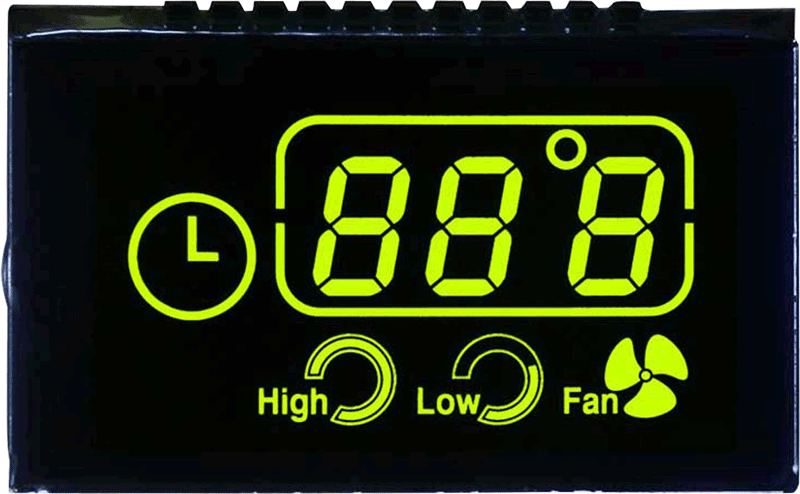
The correct term for the colored artwork here is silk printing or screen printing, not “silver printing.” Conductive silver printing is a different process and should not be confused with colored ink used for visual design.
A white backlight can illuminate the designed color treatment, while the LCD controls its defined segments. The resulting interface is not a full-color TFT with independently selectable RGB pixels. The print layer, position and transmissive openings must be confirmed on the actual assembly drawing.
In our VA work, a black printed mask can also cover fixed background areas to produce a deeper, more consistent black appearance. Unmasked segment areas still have the liquid crystal’s optical behavior. A black background alone does not establish that every LCD is VA.
What Is Polarizer Film?
A conventional LCD polarizer commonly contains a PVA-based polarizing layer protected by supporting films, with an adhesive and handling/protection layers appropriate to the product. TAC is a familiar supporting-film material, but it is not the only possible construction.
The original list included PVA, TAC, PSA, release film and protective film. PSA means pressure-sensitive adhesive. The release liner protects the adhesive before lamination; it is not necessarily retained in the finished optical stack. The temporary surface protection film must also be distinguished from the functional polarizer layers.

Polarizers are laminated in the specified orientation on the cell’s outside surfaces. Surface cleanliness, axis alignment, bubbles, scratches and adhesive condition affect appearance. Treat a bare polarizer as an optical component, not a generic plastic cover sheet.
In the conventional monochrome cell discussed here, removing a required polarizer generally prevents the intended image from being viewed normally. However, the visible image does not depend on the polarizer alone: the liquid crystal cell, illumination and full optical stack must all work together.
Positive/Negative and Transmissive/Reflective Modes
Polarizer orientation is part of establishing the selected and unselected appearance, but turning a film over is not a general method for converting a positive display to negative. Rotating an optical axis is also different from flipping the sheet front-to-back. The cell mode, compensation, illumination and complete stack must support the intended appearance.
| Optical choice | Main purpose | What to confirm |
|---|---|---|
| Positive display | Dark information on a lighter background in the intended conditions | Contrast, illumination, optical axes and cell mode |
| Negative display | Bright information on a darker background | Black-state appearance, source brightness and viewing position |
| Transmissive | Light passes through from a rear source | Backlight and complete-stack transmission |
| Reflective | Uses a rear reflector and ambient illumination | Available light, reflector and viewing conditions |
| Transflective | Combines transmitted and reflected light paths | Day/night performance and selected optical construction |
The rear optical assembly may incorporate a reflective or transflective treatment, but these modes should not be attributed to the rear polarizer film alone. There is also more than one front polarizer type or grade across LCD products.
Temperature, Handling and Enquiry Requirements
The liquid crystal is more than a generic on/off light switch: its material properties, alignment and cell geometry affect response, contrast and temperature behavior. Our commonly discussed temperature combinations and special hot/cold trade-offs are explained in the temperature section of the custom LCD guide.
That guide now also includes an original reliability-test schedule. Test temperature, electrical state, exposure duration, recovery conditions and acceptance limits must be agreed. Do not infer an extended operating rating from a storage test.
For enquiry, send the complete outline and thickness, visible area, artwork, intended optical mode, viewing position, drive conditions, connection method, temperature range, sample quantity and production forecast. If dimensions can change slightly, tell us: the sheet-layout example shows why a small change can create a useful cost-review opportunity.
Frequently Asked Questions
Is ITO glass the same as a completed LCD?
No. It is a coated substrate that must be patterned and processed with the other cell materials and optical layers to become the required display.
Are the four glass thicknesses in this article the only options?
No. They are the common historical options discussed in my monochrome projects. Confirm the current supply and complete assembly drawing.
Can a 2 mm outline reduction lower cost?
It can improve sheet utilization in some layouts. The original 56 × 82 to 56 × 80 mm example increases a simplified count from 28 to 30, but actual layout, yield and other costs must be reviewed.
Does colored printing turn a monochrome LCD into a color TFT?
No. The colors belong to the specified artwork or optical treatment; the LCD retains its defined segment or matrix control.
Can positive and negative modes be changed by flipping a polarizer?
Not as a general rule. Optical-axis orientation and the full cell/film design determine the intended result. Approve the required appearance during development.
From guide to product
Explore Related Display Products
Choose the product direction that matches the visible content, hidden assembly and integration needs.
LCD Glass Panels
Review glass outline, segment artwork, optical mode and connection requirements.
Explore product options →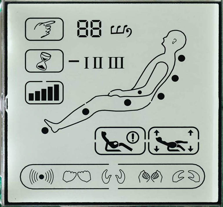
Segment LCD Displays
Develop custom digits and icons with the matched COM/SEG architecture.
Explore product options →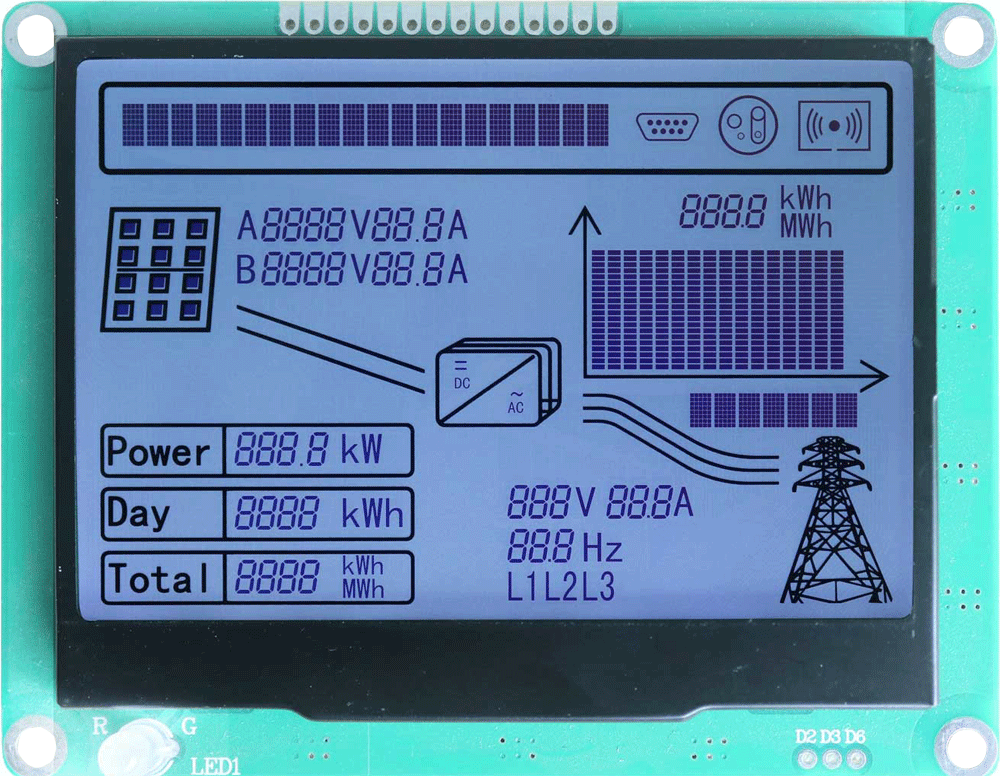
Monochrome LCD Displays
Review the complete cell, driver and assembly direction for your product.
Explore product options →Project review
Review Your Custom Monochrome LCD Requirements
Send your outline, artwork, thickness, optical mode, viewing position, drive, temperature range and quantity. DisplayMan can review a suitable cell and assembly direction.
Prefer to open the enquiry form here?
Related Engineering Guides
Custom monochrome LCD quotation requirements · Monochrome VA LCD experience and selection · LCD principles and selection
Original illustrations, layout calculations and historical commercial examples come from Greg’s earlier article. Current dimensions, processes, fees and order requirements need project-specific confirmation.