
Greg’s engineering experience
How Do We Make Round and Ring LED Backlights?
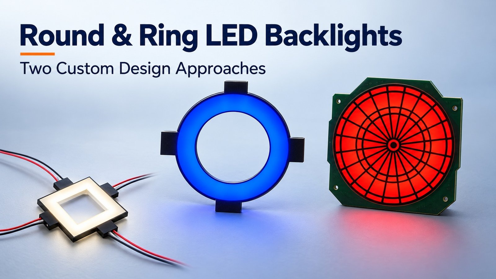
Two approaches from my projects are an edge-lit light guide with four light-entry positions, and a dedicated-board structure with a cleaner circular outline and centralized wiring. The appropriate choice depends on the visible area, hidden space, thickness, color and development requirements.
This DisplayMan guide preserves the original drawings, sample photographs and dimensions so you can compare the actual construction trade-offs before preparing a custom backlight enquiry.
Start with the Illuminated Area, Not Just a Round Outline
I wrote the original article after receiving repeated enquiries for round and ring LED backlights. The practical question was how to produce the required illuminated shape while leaving room for LEDs, electrical connections and the housing.
A round backlight illuminates a disk-shaped area. A ring backlight has an illuminated annulus around a central opening. In either case, distinguish the visible illuminated area from the complete outline: the LEDs, mask, PCB or connection edge may extend beyond what the user sees.
The two approaches below are taken from my original designs. Their dimensions explain those examples; they are not fixed rules for every custom backlight.
The Rectangular Backlight Used as Our Starting Example
The original rectangular example makes the basic structure easier to understand before changing the shape.
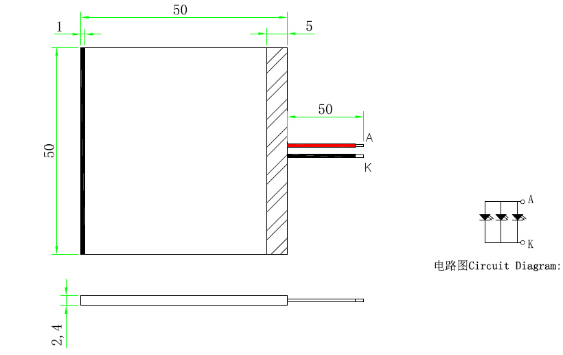
| Item | Original example |
|---|---|
| Overall outline | 50 × 50 mm |
| Viewing area | 44 × 50 mm |
| Light-shielding area | 5 mm as described in the original drawing discussion |
| Light guide plate | 2.0 mm |
| Total backlight thickness | 2.4 mm |
| Light sources | Three SMD LEDs connected in parallel |
| Drive voltage recorded | 3.0 V |
The original text lost the multiplication symbols in the 50 × 50 and 44 × 50 dimensions. Also, the nominal 5 mm masked region should not be used to reconstruct all outline allowances by subtraction: use an approved dimensioned drawing for a new design.
The light-shielding area is where the LEDs and light-entry region are hidden. Without a suitable mask, the source area can appear as a bright spot instead of blending into the illuminated surface. This is a deliberate optical and mechanical allowance, not wasted space that can always be removed.
The 3.0 V figure belongs to that sample arrangement. For a new backlight, confirm rated current, LED characteristics and the current-control circuit as well as voltage.
Option A: Edge-Lit Ring with Four Light-Entry Positions
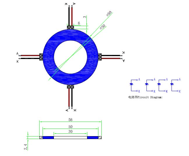
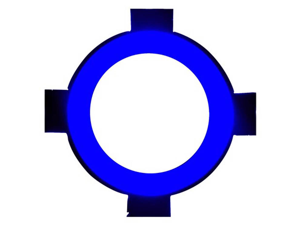
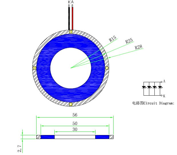
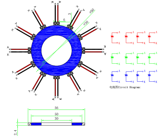
In Option A, we position light sources at 12, 3, 6 and 9 o’clock around the light guide. The illustrated blue backlight has a central opening.
| Item | Option A example |
|---|---|
| Optical approach | Edge-lit light guide |
| LED positions | Four positions, at 12, 3, 6 and 9 o’clock |
| Light-shielding region | Approximately 3 mm in the original example |
| Light guide plate | 2.0 mm |
| Total thickness | 2.4 mm |
| Original connection arrangement | Four anodes and four cathodes brought out separately |
The advantage in my original design was that existing LED PCB arrangements could be reused instead of developing a complete dedicated circular PCB for each outline. Reuse still depends on physical fit, light coupling and assembly constraints; it is not automatic for every diameter.
The drawback is visible in the drawing: four local light-source or masking regions interrupt the otherwise circular outline. If the housing cannot hide them, the complete part does not look like a simple ring even though the viewing area is ring-shaped.
For a product with enough hidden space around the display window, this can be a practical route. Check the full assembly envelope rather than judging only the illuminated opening.
Option B: A Dedicated PCB for a Cleaner Ring Outline
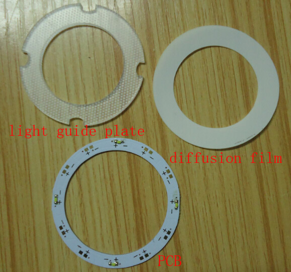
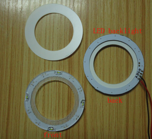
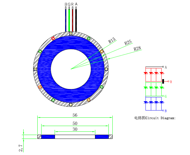
Option B uses a dedicated board and a backlighting arrangement that produces a cleaner ring outline with a simple wire connection.
| Item | Option B example |
|---|---|
| Optical approach | Bottom/direct-lit arrangement as described in the original design |
| Light-shielding region | Approximately 3 mm |
| Illuminated ring width | 10 mm in the original example |
| LEDs | Four SMD LEDs connected in parallel in the single-color example |
| Light guide/optical plate | 1.5 mm |
| PCB thickness | 0.8 mm |
| Diffusion film | 0.2 mm |
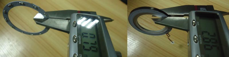
| Complete thickness recorded | Approximately 2.7–2.8 mm |
| Single-color external connection | One anode and one cathode |
The named layers total 2.5 mm. The original complete thickness was about 2.7–2.8 mm; the final drawing must account for the remaining assembly layers and tolerances rather than treating the layer sum as the finished thickness.

The benefit is the cleaner circular form and consolidated electrical connection. The trade-off is that a change in ring dimensions can require a new dedicated PCB and revised optical parts. That development work belongs in the initial quotation review.
Comparing the Two Approaches
| Decision point | Option A: edge-lit example | Option B: dedicated-board example |
|---|---|---|
| Complete outline | Four local source/mask regions need hidden space | Cleaner ring outline |
| Board development | Existing LED board arrangements may be reusable | Dedicated PCB required for the design |
| Original thickness | 2.4 mm | Approximately 2.7–2.8 mm |
| Original single-color wiring | Four separate anode/cathode pairs | One external anode/cathode pair |
| Diameter changes | Review light guide and fit; board reuse may be possible | Review PCB and optical redesign |
| Main reason to consider it | Available hidden space and reuse of an existing arrangement | Cleaner outline and centralized wiring |
In my original comparison, Option A made efficient use of light entering along the intended illumination direction. As ring size increased, the Option B arrangement could need more LEDs to reach the target brightness.
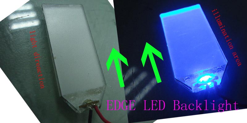
That is a comparison of these constructions, not a universal efficiency ranking between all edge-lit and direct-lit backlights. Useful output depends on the LED package, coupling, illuminated area, optical pattern, diffusion and operating current. Compare prototypes at the same measured brightness and uniformity before drawing a power or cost conclusion.
For more on the optical approaches, see our edge-lit vs bottom-lit LED backlight comparison.
Wiring: Why the PCB Layout Matters
The original Option A brought out four anodes and four cathodes. Connecting these separately adds wiring and assembly work. In Option B, the dedicated PCB collects the single-color connections into one anode and one cathode.
Those counts belong to the illustrated connection layouts. They are not inherent limits of edge lighting: a redesigned PCB or FPC can change the way the sources are interconnected and brought out.
For parallel LED arrangements, confirm appropriate branch current control and current sharing. Do not approve the circuit only from the number of wires or a nominal supply voltage. Our custom LED backlight requirements guide provides the broader electrical and mechanical enquiry checklist.
Multicolor Rings and RGB Control
When multiple colors are needed, the original Option A arrangement becomes more complicated because each distributed light-source position needs its electrical connections.
In the original RGB version of Option B, the dedicated board simplifies the external connection to one common anode and three cathodes for red, green and blue. That makes color control easier to integrate in this design.
Other RGB components may use a common-cathode arrangement or a different control interface, so confirm the actual circuit. A four-wire RGB connection also does not mean that each position around the ring is individually addressable.
Mixing the red, green and blue channels can produce many selectable colors rather than requiring a separate LED type for each finished color. The controller determines channel intensity and the resulting appearance.
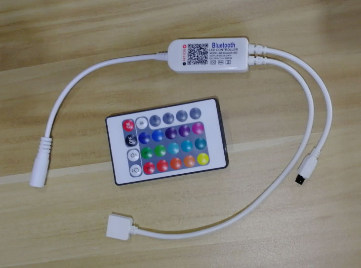
The original example uses a color controller with a remote. A production product may instead use its own electronics, but the driver, current, dimming method and desired color transitions must still be specified. Review the LED backlight color explanation for the related principle.
What to Check on the First Sample
- Visible shape: Does the housing hide the LED and masking regions? Is the inner opening correctly aligned?
- Uniformity: Check bright points, dim sections, the inner edge and the joins between light-entry regions.
- Brightness: State whether the measurement is at the backlight surface or through the completed LCD and cover.
- Color: Review the actual white point or RGB mix at the intended drive and brightness.
- Mechanical fit: Check total thickness, mounting, cable exit, tolerances and pressure from the enclosure.
- Electrical behavior: Confirm current, driver compatibility, temperature rise and any dimming requirements.
A ring that looks attractive in a photograph can still need optical adjustment when installed behind an LCD or a printed mask. Approve the representative assembly, not just an exposed lighting sheet.
Prepare a Round or Ring Backlight Enquiry
Send the following information before quotation:
| Requirement | Information to provide |
|---|---|
| Shape | Round disk or ring; drawing of the required illuminated area |
| Dimensions | Outer diameter, inner diameter, visible ring width and full assembly envelope |
| Thickness | Maximum complete thickness, not just optical plate thickness |
| Hidden space | Permitted LED positions and light-shielding areas |
| Optical target | Brightness measurement position, uniformity and color |
| Electronics | Supply, rated current target, single color or RGB, controller and dimming |
| Integration | LCD or cover stack, mounting and wire/FPC/connector exit |
| Commercial scope | Sample quantity, production quantity and project schedule |
My starting point is to compare the required visible form with the available hidden space. That usually makes the choice between an edge-lit arrangement and a dedicated-board structure much clearer.
Frequently Asked Questions
Does a ring-shaped viewing area require a perfectly circular complete assembly?
No. Option A illustrates a ring-shaped illuminated area with local source regions outside the clean circular form. The housing can hide those regions if space allows.
Is the dedicated-board option always better?
No. It gives the illustrated design a cleaner outline and centralized wiring, but involves a dedicated board and different thickness and optical trade-offs. Choose against the actual assembly requirements.
Can the dimensions change without new development?
Sometimes existing source-board arrangements can be reused, but a changed light guide still needs review. A dedicated ring PCB commonly needs redesign when its geometry changes.
Can the backlight show many colors?
An RGB arrangement can mix channels to produce many selectable colors. Specify whether you need the whole ring to change together or independent control of different regions.
Are these dimensions standard products?
They are examples from my original project explanation. A new design needs its own confirmed drawing, optical specification and electrical arrangement.
From guide to product
Explore Related Display Products
Choose the product direction that matches the visible content, hidden assembly and integration needs.
LED Backlights
Review custom shapes, optical targets and electrical arrangements.
Explore product options →
FPC / Cable Assembly
Review flexible circuit and connection requirements where the backlight structure needs them.
Explore product options →
Monochrome LCD Displays
Develop the illumination together with a segment or dot-matrix LCD assembly.
Explore product options →Project review
Review Your Round or Ring Backlight Requirements
Send the outer and inner diameters, illuminated area, hidden space, thickness, brightness, color, supply and quantity. DisplayMan can review a practical round or ring backlight structure.
Prefer to open the enquiry form here?
Related Engineering Guides
Custom LED backlight quotation requirements · Edge-lit vs bottom-lit backlights · Custom round LCD module design approaches
Dimensions, photographs and construction comparisons come from Greg’s original round and ring backlight discussion. New designs require their own approved drawings and test conditions.