Greg’s backlight engineering guide
Should You Choose Edge-Lit or Direct-Lit?
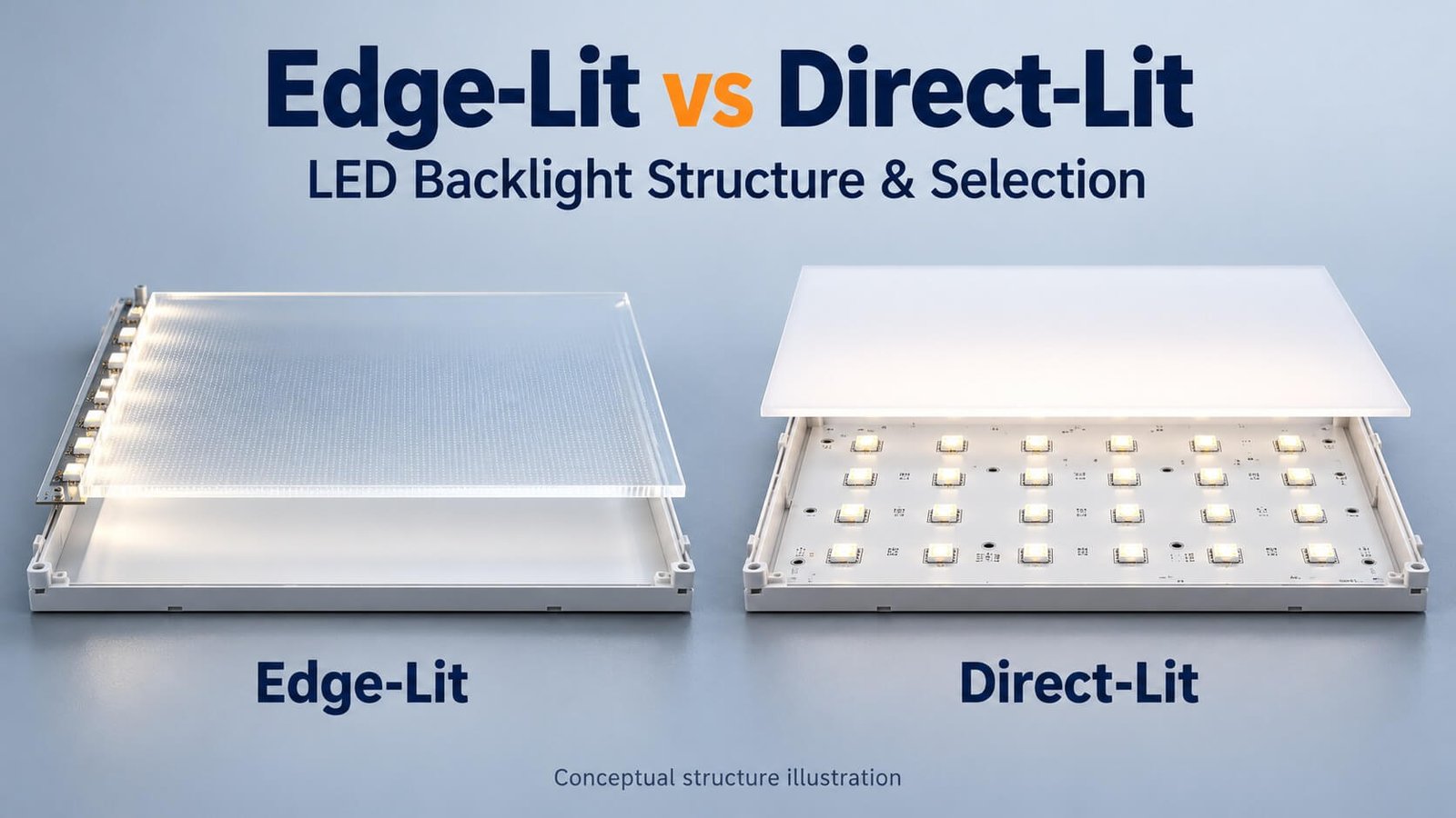
Edge-lit backlights use LEDs at a light-guide edge; direct-lit backlights position an LED array behind the illuminated area. The right choice depends on thickness, useful brightness, uniformity, thermal design, available space and cost.
This DisplayMan guide retains my original five construction images and practical experience, while separating project examples from universal rules. The full optical comparison belongs here; the companion quotation guide covers the information needed to price a custom assembly.
How Edge-Lit and Direct-Lit Backlights Work
An edge-lit backlight places LEDs along one or more edges of a light guide plate. The guide transports the light and uses extraction features to distribute it across the illuminated area. A rear reflector and other optical films help manage the output.
A direct-lit backlight, called bottom-lit in my original article, places an LED array behind the illuminated surface. Light spreads across a mixing distance and passes through the selected diffusion and optical layers. It does not necessarily need the same kind of light guide used in an edge-lit assembly.
The important difference is the light-source position and optical path. Both are LED backlights; neither is a self-emissive LED display panel.
Original Direct-Lit Examples: LED Pitch and Mixing Distance
The original photographs show a direct-lit construction, its depth and the LED arrangement. They are useful because they explain why a backlight cannot always become thinner simply by reducing housing depth.
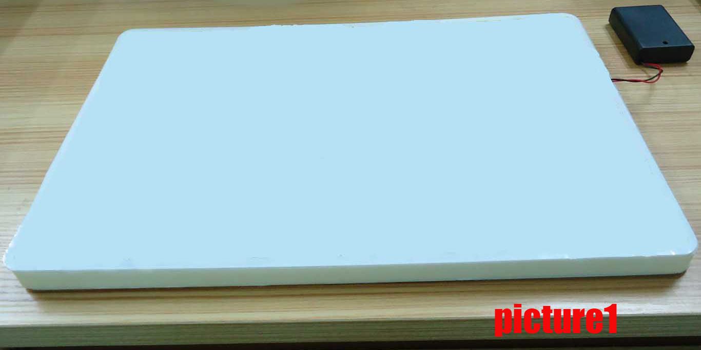
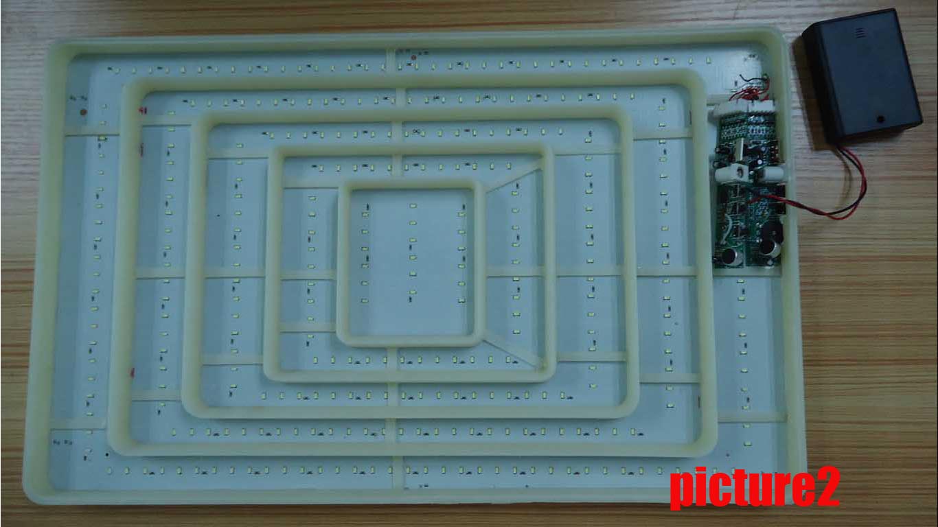
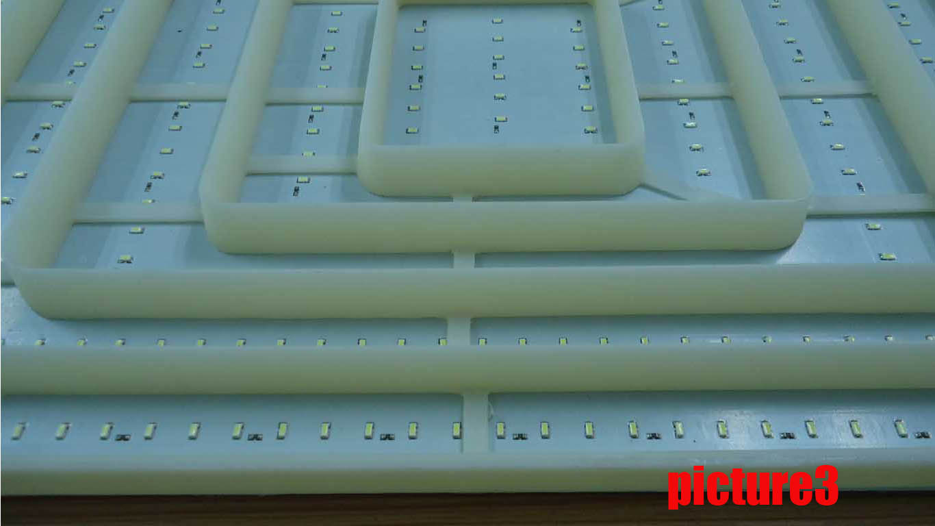
If the LEDs are too widely spaced for the available mixing distance, visible bright points and dark regions can appear. Bringing the diffuser closer to the array without changing the source optics or spacing can make those patterns more obvious.
Possible adjustments include LED pitch, emission pattern, lenses, optical distance and the diffusion stack. Each changes power, cost or mechanical requirements. A denser LED array can help a thin design, but useful uniformity still requires optical development and sample validation.
My old article described direct-lit assemblies several times thicker than the small edge-lit units I was handling. That was an observation about those constructions, not a universal thickness ratio. Likewise, a dedicated board and plastic tool were part of particular designs rather than compulsory elements in every direct-lit backlight.
Original Edge-Lit Examples: Cut and Molded Light Guides
The first original example uses a cut light guide with printed extraction dots and DIP LEDs. The second uses a molded guide with non-printed extraction features and SMD LEDs.
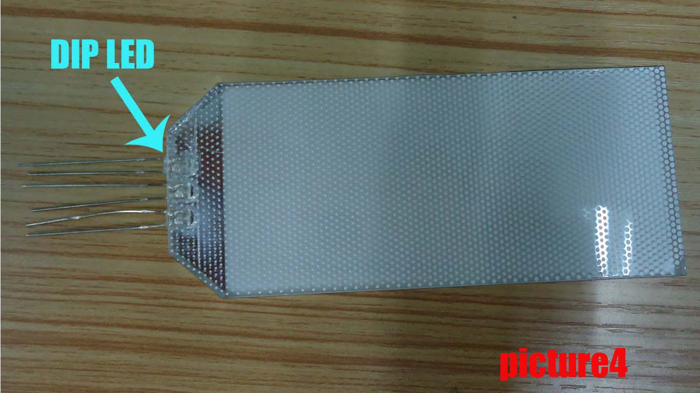
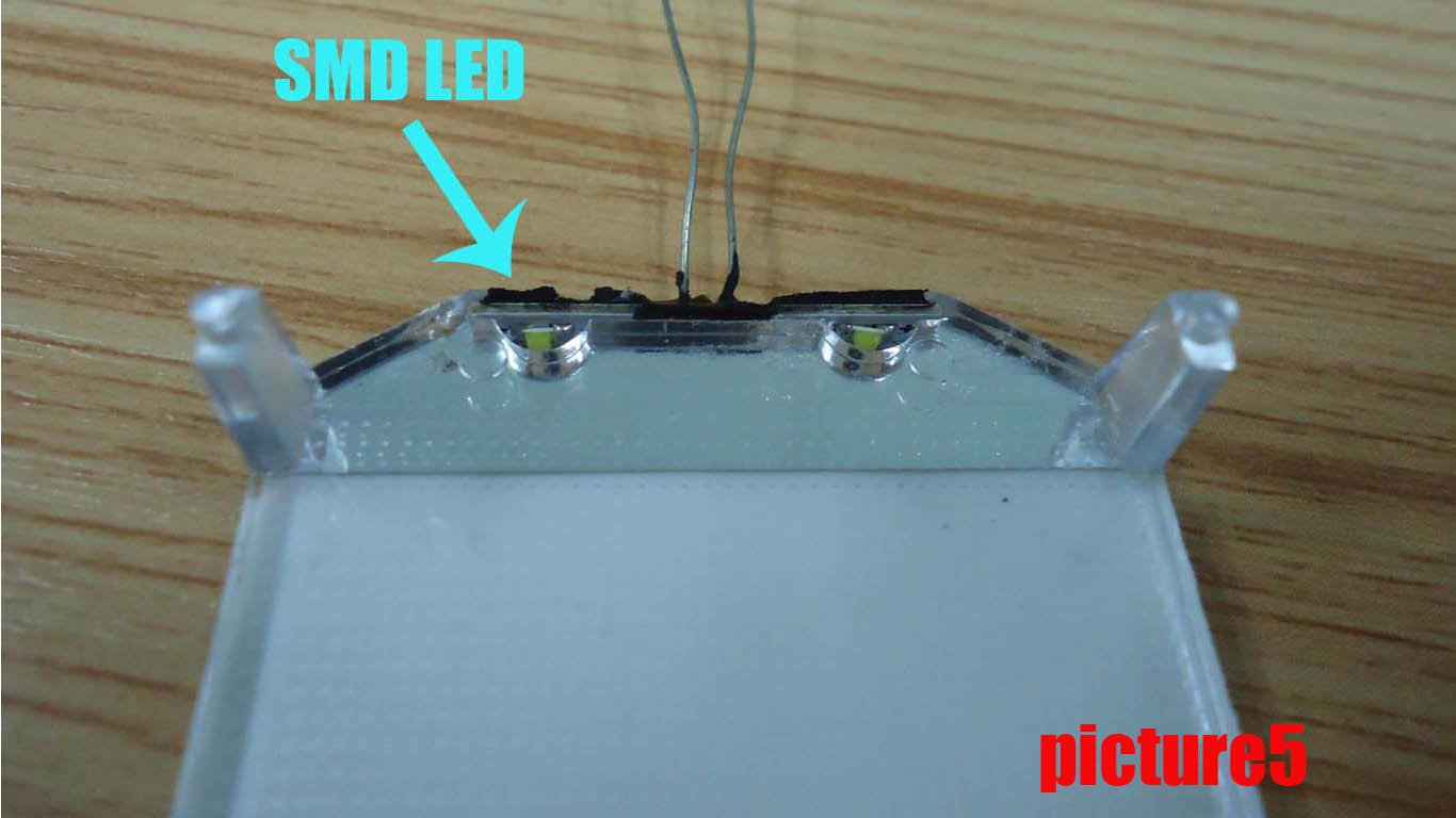
These are examples of combinations we used, not rules linking DIP only to cutting or SMD only to molding. The source package, light-entry edge, guide pattern and complete stack must be designed together.
In my earlier small-module projects, edge-lit assemblies around 1–5 mm thick were common starting points. That made them attractive where the customer wanted a thin assembly and an economical construction. The actual thickness depends on the guide, film stack, LED package, board or FPC, adhesive and enclosure allowances.
Edge-lit backlights are not limited to small displays. Larger designs are feasible when the light guide, source arrangement and mechanical support are suitable. Uniformity can become difficult if the guide pattern and light input do not match the illuminated area, but poor large-area uniformity is not an unavoidable property of edge lighting.
Compare Thickness, Uniformity, Brightness and Cost
| Selection point | Edge-lit backlight | Direct-lit / bottom-lit backlight |
|---|---|---|
| LED position | At one or more guide edges | Behind the illuminated area |
| Main optical approach | Light coupling and extraction through a guide | Source spreading and mixing through the optical distance and films |
| Thickness | Often useful where a thin guide-based stack fits | Mixing distance and lenses can set the depth requirement |
| Uniformity risks | Bright edges, dim regions, visible extraction pattern | Visible LED points, bright/dark stripes or insufficient mixing |
| High brightness | Review guide input, LED current and heat at the edges | Review array density, current, thermal path and optics |
| Mechanical design | Guide support, flatness and edge-source alignment | Array support, optical spacing and diffuser stability |
| Development cost | Guide process/tooling, source boards and films | LED board/array, optics and housing structure |
| Local dimming | Depends on the particular source and guide architecture | Suitable arrays can be divided into independently controlled zones |
My original article quoted some small edge-lit examples at half to one-third the cost of the direct-lit alternatives. That is retained as historical project context, not a current quotation rule. The same outline can produce a different cost ranking when brightness, quantity, material, thickness and control requirements change.
The old comparison also included individual television LED counts, power consumption and cabinet thickness. Those values do not establish present-day design targets. Compare the complete optical and electrical specification rather than the source position alone.
Brightness and Power: Compare the Same Useful Output


A useful comparison measures luminance at the same surface, with the same target uniformity, color, operating temperature and dimming condition. Backlight-surface brightness is not the brightness seen through an LCD and cover glass.
More LEDs can provide more available light, but doubling their number does not guarantee double useful front luminance. Current, thermal behavior, source coupling and optical losses affect the result.
Edge-lit is not automatically lower-power, and direct-lit is not automatically brighter. Start from the required useful output, then compare the proposed guide, array and driver as a complete system.
Thermal Design and Mechanical Integration
Edge lighting concentrates sources and associated heat near the guide edges. Direct lighting distributes the sources across an array, but can still require careful thermal paths and enough room for the optics.
Review LED current, PCB material, thermal interfaces, housing and ambient temperature. Test a representative enclosure until its operating condition stabilizes; an exposed backlight on a workbench may behave differently after integration.
Mechanical pressure, warped parts or incorrect optical spacing can also change uniformity. Check film orientation, guide alignment, cable routing and the supported optical area during assembly.
Direct-Lit Is Not the Same as Local Dimming
A direct-lit backlight may operate as one uniformly driven array. It becomes a local-dimming system only when its design includes independently controlled zones and suitable control electronics.
Local dimming reduces or switches off illumination behind dark image regions. It can improve black levels and image contrast, but bright objects on dark backgrounds can still show halos because a zone commonly covers multiple LCD pixels.
For color-display projects needing more precise backlight control, review our Mini-LED backlit LCD displays. Smaller LEDs alone do not establish zone count, algorithm quality or zero blooming.
For a conventional small monochrome backlight, those advanced controls may add unnecessary complexity. The appropriate structure depends on the actual application.
Which Structure Would I Start With?
| Project situation | Starting direction to review | What could change the decision |
|---|---|---|
| Thin small instrument or monochrome LCD | Edge-lit light guide | Source-mask space, guide shape, brightness and connection constraints |
| Custom ring or irregular illuminated area | Compare guide-based and dedicated-board designs | Visible outline, hidden source regions, thickness and RGB wiring |
| Large-area or high-output assembly | Evaluate both; direct lighting can be practical | Required depth, uniformity, power, thermal design and cost |
| Color LCD with local-dimming requirements | A suitable zoned architecture | Zone control, optical distance, halos, panel compatibility and budget |
| Existing tight enclosure | Review the full mechanical stack before choosing | Tooling, connector position, mounting and allowable heat |
My original preference for edge lighting reflected the enquiries I handled then. It should not be treated as a rule that direct lighting is unsuitable. I would now ask for the application, visible area, complete thickness, useful brightness and quantity before recommending either route.
Our round and ring LED backlight examples show how the visible shape and connection layout can change the choice. For complete quotation details, use the custom LED backlight requirements guide.
Sample Comparison and Enquiry Checklist
Send the outline drawing, illuminated area, hidden source space, thickness limit, brightness target, measurement position, color, supply and quantity. Include the LCD/cover stack and mounting environment where applicable.
Compare samples under consistent conditions:
- Measure center and multiple edge/corner locations with a defined uniformity calculation.
- Record luminance, color, input current and power at the selected operating setting.
- Check hot spots and visible patterns through the intended LCD or cover.
- Review daytime and night appearance if the product needs dimming.
- Check temperature and optical stability in the representative enclosure.
- Approve the complete outline, masking region, mounting and cable exit.
If the structure is undecided, provide requirements rather than selecting a technology name first. DisplayMan can review a feasible construction and explain which items require custom development.
Frequently Asked Questions
Is “bottom-lit” the same as “direct-lit” in this article?
Yes. Both refer here to LEDs positioned behind the illuminated area. The exact optical construction still needs to be specified.
Can an edge-lit backlight be used in a large display?
Yes. Its suitability depends on the guide, LED arrangement, uniformity, brightness and mechanical requirements. The old statement that it is only suitable for small sizes was too broad.
Does direct lighting always give better uniformity?
No. LED pitch, source optics, optical distance and diffusion must be matched. Poorly mixed direct lighting can show visible bright points and dark regions.
Which approach is cheaper?
There is no fixed ratio. Compare the actual materials, optics, development, quantity and performance requirements.
Does a direct-lit LED backlight eliminate light leakage?
No. A conventional illuminated LCD can still transmit light in its black state, and assembly issues can create localized leakage. Local dimming can reduce dark-region illumination but is a separate system feature.
From guide to product
Explore Related Display Products
Choose the product direction that matches the visible content, hidden assembly and integration needs.
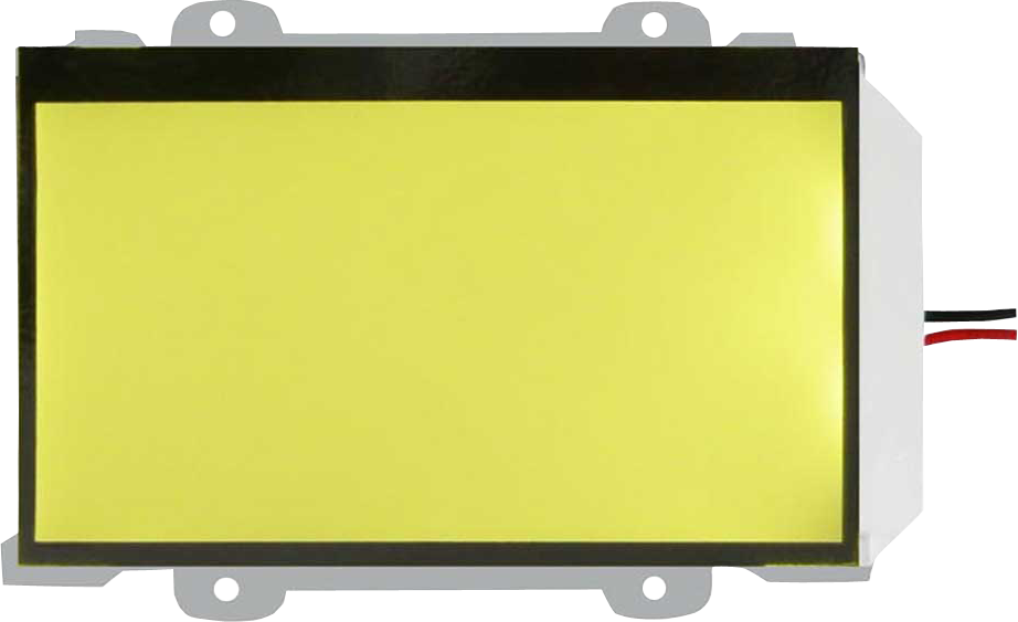
LED Backlights
Discuss a custom light guide or LED array around the required optical and mechanical performance.
Explore product options →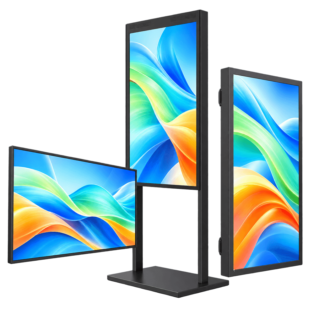
High Brightness TFT LCD Displays
Review the brightness requirement at the finished LCD surface.
Explore product options →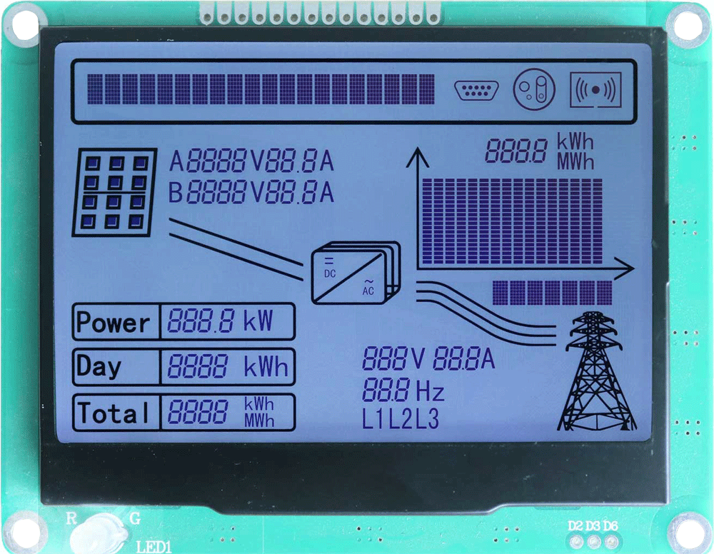
Monochrome LCD Displays
Match the backlight structure to a custom segment or dot-matrix LCD assembly.
Explore product options →Project review
Review Your Backlight Structure Requirements
Send your application, outline, illuminated area, thickness, brightness, color, supply and quantity. DisplayMan can review an edge-lit or direct-lit construction.
Prefer to open the enquiry form here?
Related Engineering Guides
Custom LED backlight quotation requirements · Round and ring backlight designs · LCD backlight bleeding and assembly checks
Original images and historical observations come from Greg’s earlier edge-lit and bottom-lit comparison. Confirm each new construction through approved drawings and sample measurements.