Quick answer
What Is Backlight Bleeding, and When Does It Matter?
LCD backlight bleeding is localized unwanted light visible on dark content, commonly near edges or corners. It must be distinguished from IPS glow, general black-level limitations and other uniformity issues. Assess it at controlled brightness, viewing angle and ambient light, then compare the result with the application’s agreed acceptance criteria.
For OEM projects, inspect both the module and the final enclosure. DisplayMan reviews display selection, mechanical integration and sample requirements together for TFT LCD, high-brightness LCD and transparent LCD systems.
What Is LCD Backlight Bleeding?
Backlight bleeding is unwanted, localized light visible on a dark LCD image, often near an edge or corner. An LCD modulates a separate light source rather than emitting light independently at each pixel. Its black state is therefore not perfectly opaque. However, uneven bright patches should not automatically be dismissed as an unavoidable feature of every LCD.
Separate two observations: a generally elevated black level, which relates to panel contrast and viewing conditions, and a localized flare, which may involve the panel, optical stack or assembly. A photograph alone rarely identifies the exact cause.
A small difference noticed only in an unusually dark room may be acceptable for one installation, while a similar pattern behind a dark instrument interface could be unacceptable. Price and panel brand do not replace an agreed inspection method.
For the underlying structure, see What Is TFT LCD?.
Backlight Bleeding vs IPS Glow, Mura and Other Defects
Use several patterns and viewing positions before assigning a defect name. These are practical clues, not a substitute for engineering diagnosis.
| Observation | Possible explanation | Useful next check |
|---|---|---|
| A localized bright flare near an edge on black content | Backlight leakage or assembly-related nonuniformity | Compare the same position before and after approved enclosure installation |
| A broad pale glow that changes noticeably with viewing position | IPS glow or other angle-dependent black-state behavior | Move to a centered, normal viewing position and repeat |
| Cloudy or tinted patches on gray or white content | Mura, stress, cell or optical-stack nonuniformity | Compare black, gray and white patterns at controlled settings |
| A halo around a bright object on a dark background | Local-dimming blooming, where supported | Repeat with the same local-dimming mode documented |
| One small fixed bright dot | Pixel or subpixel defect | Inspect full-screen red, green, blue, white and black patterns |
| Light visible through an enclosure joint, outside the image area | Housing or masking leakage | Inspect the mechanical light path and shielding |
IPS glow and local leakage can coexist. For panel-mode differences, see TN vs IPS vs VA. Dell also distinguishes angle-dependent IPS glow from light leakage in its monitor guidance; that distinction is useful, but individual product acceptance rules remain product-specific. [1]
Why Does Backlight Bleeding Happen?
Mechanical stress and mounting
Uneven bezel loading, an enclosure that twists the module, misplaced pads or mounting features that contact sensitive areas can change the optical appearance. A sample that looks acceptable on a bench may behave differently after installation.
Review the module drawing, support points, clearances and supplier handling instructions. Screw torque and cushioning compression must be defined for the actual assembly; there is no universal torque value for all LCD modules.
Light shielding and optical-stack fit
Depending on the design, masking, reflective materials, optical-film positioning and frame fit can influence where light becomes visible. A missing or displaced shield can create an unwanted light path. Optical films that are displaced or constrained may produce unevenness that is better described as mura rather than simple edge leakage.
Panel characteristics and viewing conditions
LCD black-state transmission varies with the panel mode and viewing angle. Increasing backlight output can make residual black-state light more apparent, while room reflections can hide or imitate defects. Neither effect establishes whether a particular sample meets its specification.
Transport, installation and temperature
Check whether the pattern appeared after unpacking, installation or thermal operation. Damage, enclosure deformation and temperature-dependent mechanical changes are possible investigation paths. Record the sequence rather than assuming shipping or temperature is the cause.
The liquid-crystal alignment layer is part of panel manufacturing, but describing all backlight bleeding as an inevitable result of rubbing that layer is not a useful root-cause explanation.
How to Test Backlight Bleeding Repeatably
Use two separate checks: diagnostic inspection to reveal the pattern, and acceptance inspection under the agreed application conditions. A dark-room image at maximum brightness can help locate an issue, but it should not silently become the pass/fail requirement for a product intended for a different environment.
- Identify the exact sample. Record the panel/module number, revision, serial or batch number, controller and firmware where relevant.
- Set a repeatable operating state. Use the intended power supply and allow stabilization according to the product procedure. Record brightness, image mode, automatic brightness control, dynamic contrast and local-dimming settings.
- Control the environment. Record ambient illuminance at the display, room reflections, viewing distance and viewing direction. Use the conditions agreed with the supplier for acceptance.
- Display full-screen patterns. Start with black, then use gray, white and RGB patterns. Include the actual interface or signage content to assess practical impact.
- Inspect from the normal position. Then change viewing position to investigate angle-dependent glow. Do not compare samples photographed from different angles as though the conditions were identical.
- Compare installation states. Qualified personnel can compare the module in its approved support arrangement with the completed enclosure. Do not operate a loose module in an unsafe or unsupported configuration.
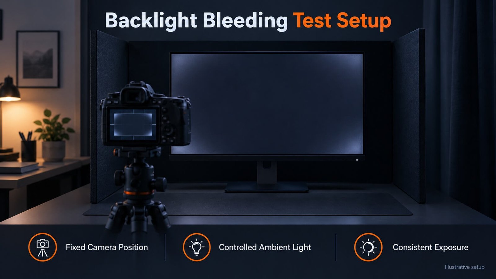
- Capture consistent evidence. Use a fixed camera position and manual exposure where available. Keep shutter speed, ISO, aperture and white balance consistent between samples. Disable automatic night-mode enhancement for comparison photographs.
- Document the result. Mark the location, size and appearance of the affected area, plus whether it is visible with real content under the acceptance conditions.
A camera can exaggerate faint leakage through long exposure or automatic processing. Conversely, a short exposure can hide it. Photographs support a report; they do not replace controlled viewing or calibrated measurements when numerical acceptance is required.
What Is an Acceptable Amount of Backlight Bleeding?
There is no single number in this guide that applies to every LCD module, monitor and application. Specify acceptance with the supplier before production rather than relying on an unspecified “normal amount.”
| Item to agree | What the purchase specification should record |
|---|---|
| Viewing conditions | Ambient illumination, observation position, viewing distance and inspection time |
| Operating settings | Brightness or measured white luminance, image mode and relevant adaptive settings |
| Test content | Black/gray patterns and representative application content |
| Permitted appearance | Defined zones, affected area, contrast or an approved comparison sample |
| Numerical method, if needed | Instrument, measurement locations, geometry, ambient control and pass/fail calculation |
| Production handling | Sampling plan, defect classification and process for disputed samples |
A statement such as “less than 4 cd/m²” is incomplete without an identified standard or agreed specification and its measurement conditions. cd/m² measures luminance, not luminous flux. It should not be presented as a universal legal allowance.
An approved reference sample can make visual evaluation more consistent, but it should be paired with documented conditions and retained identification. AQL sampling determines how a batch is sampled and accepted; it does not define the optical limit by itself.
How Can Backlight Bleeding Be Reduced?
For OEM work, identify the failure mechanism before changing materials or replacing the panel.
- Compare against the approved sample. Confirm that the module revision, controller settings and operating brightness match.
- Check the enclosure drawing. Review flatness, support points, bezel overlap and clearance around the active area and module edges.
- Review assembly control. Check fastener sequence, specified torque, pad placement and compression. Investigate whether variation follows an assembly station or component batch.
- Inspect shielding and optical parts. Look for missing, shifted or incorrectly fitted components through the approved inspection process.
- Validate a controlled change. Change one variable at a time and repeat the same optical and mechanical checks.
- Confirm reliability. An improvement on the bench should survive the applicable thermal, transport and installation checks before production release.
Do not press or “massage” the display, loosen consumer monitor screws indiscriminately, or apply heat as a repair method. Such actions can damage the cell, alter the assembly or obscure the original fault. For finished products, follow the supplier’s service procedure.
Reducing brightness may make a pattern less visible, but it is only a valid product solution if the resulting brightness still meets the project requirement.
TFT LCD, High-Brightness LCD and Transparent LCD Projects
Standard TFT LCD modules
Evaluate the module and the final assembly. A display approved before fitting a touch panel, cover glass or enclosure may require another check afterward. Consider reflections and viewing angle alongside black-state uniformity.
Explore TFT LCD Displays when selecting modules for equipment interfaces and OEM products.
High-brightness LCD displays
Test at the intended working brightness and thermal condition. If black-state transmission remains otherwise similar, stronger backlighting can increase the absolute light visible in dark regions. This does not mean every high-brightness panel has poor uniformity.
Define both daytime readability and any dimmed/night operation. Check brightness control, heat management, front optics and installation together. See High Brightness TFT LCD Displays.
Transparent LCD display systems
A transparent LCD showcase is not evaluated like an opaque monitor with its own conventional enclosed backlight. The cabinet lighting, illuminated objects, rear background and viewing direction contribute to the visible result.
Check unintended light around the panel and cabinet joints, as well as lighting uniformity across the display and product area. A dark pixel region modulates transmitted light; it should not be assumed to produce the same appearance as black on a conventional monitor.
Explore Transparent LCD Displays and the Transparent LCD vs OLED Cabinet Guide for system-level selection.
Does OLED Have Backlight Bleeding?
OLED does not use an LCD backlight, so it does not have backlight bleeding from that mechanism. It can still have other image-quality issues, including near-black nonuniformity, image retention or aging-related changes. Switching technology does not remove the need for an acceptance specification.
For a broader comparison, read LCD vs OLED Displays. For a transparent cabinet, also evaluate lighting, background visibility and the intended content rather than selecting only on the basis of conventional black levels.
OEM Sample Approval and Failure Report Checklist
Before ordering, share the application, normal viewing environment, display size, required luminance, interface, quantity and enclosure drawings. If dark-scene performance is important, state that early.
A useful failure report includes:
- Model, revision, batch identification and quantity affected versus quantity inspected.
- Whether the issue was observed before installation, after assembly, after transport or after a specified reliability test.
- Brightness settings, test patterns, power conditions and stabilization procedure.
- Ambient conditions, viewing geometry and repeatable photographs of both the issue and the approved reference.
- Evidence from black, gray and real application content, with marked defect locations.
- The agreed acceptance requirement and the requested next action: investigation, replacement or controlled design review.
DisplayMan can review the LCD module and integration requirements together. A remote photograph can support initial triage; confirming the cause or conformity may require the physical sample and the agreed inspection procedure.
Frequently Asked Questions
Is backlight bleeding always a manufacturing defect?
A visible dark-screen difference can involve panel characteristics, viewing angle or assembly. Determine which phenomenon is present, then compare it with the product’s agreed acceptance conditions. Do not label every IPS glow pattern as an assembly defect.
Will backlight bleeding get worse over time?
There is no universal progression. An existing pattern does not prove future failure. If the appearance changes, document operating conditions, installation and possible damage, then have the supplier investigate.
Can software fix backlight bleeding?
Software cannot repair a mechanical light path or stressed optical assembly. Brightness controls and local dimming can change the visible result on compatible products, but may also affect image appearance. Evaluate any setting under the actual use conditions.
Is a dark-room test enough to reject a batch?
Only if that test and its limits form part of the agreed acceptance procedure. Diagnostic conditions and contractual acceptance conditions should be clearly distinguished.
Is a more expensive LCD guaranteed to have no bleeding?
No. Ask for suitable optical specifications, a representative sample and final-assembly validation. Price alone is not an inspection criterion.
Should I choose OLED instead?
Consider contrast, brightness, operating schedule, static content, lifetime requirements, interfaces, size and budget. Avoid choosing an entire display technology to solve an issue that may be caused by an enclosure or assembly process.
From guide to product
Explore Related Display Products
Explore LCD product directions with optical performance and installation requirements reviewed together.

TFT LCD Displays
Explore color modules for OEM interfaces, with mechanical, electrical and optical requirements reviewed together.
Explore product options →
High Brightness TFT LCDs
Compare brighter module options while checking reflection control, power and thermal constraints.
Explore product options →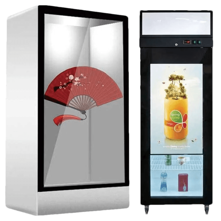
Transparent LCD Displays
Review see-through display directions for showcases, refrigeration and other engineered systems.
Explore product options →Project review
Review Your LCD Module and Installation Requirements
Send your application, module size, working brightness, quantity and enclosure drawings. If a sample shows uneven light, include its settings, installation state and repeatable photographs for an initial engineering review.
Prefer to open the enquiry form here?
Technical References and Further Reading
- Dell: How to distinguish IPS glow and light leakage
- Dell: Troubleshooting light leakage or light bleeding on a monitor
- EIZO: Monitor test patterns and image-quality checks
Manufacturer guidance helps identify optical phenomena. Its inspection conditions apply to the specified products and do not create a universal acceptance limit for all OEM modules. Agree the exact inspection procedure with your supplier.