
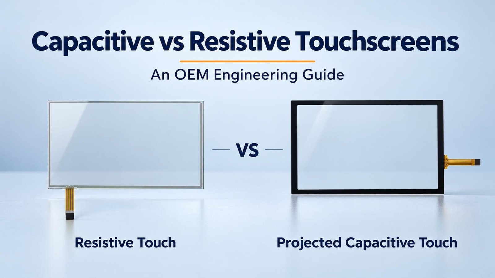
Buying Guides & Project Review · Touch Technology
Choose the Touch Technology Around the Operator
Start with PCAP for light finger input, multi-touch and glass-front interfaces. Evaluate resistive touch for deliberate pressure input, passive stylus use or a compatible legacy replacement.
Gloves, liquids, electrical noise, optics and host integration can change the decision. DisplayMan helps compare the complete sensor, controller and display assembly against the way your product will actually be used.
1. Capacitive or Resistive: Start with the Required Input
Choose around how people will operate the product. Bare fingers, industrial gloves, a passive plastic stylus and an active pen create different requirements. The touchscreen must also match the display, host, enclosure and operating environment.
For many modern interfaces, projected capacitive touch (PCAP) is a useful starting point for light finger input, multi-touch and a glass front. Resistive touch remains relevant for deliberate pressure input, passive stylus operation and replacement of established equipment.
Neither technology makes an assembly automatically waterproof, sunlight-readable or immune to electrical noise. DisplayMan reviews these requirements at the complete display-and-touch level.
2. How Modern Capacitive Touchscreens Work
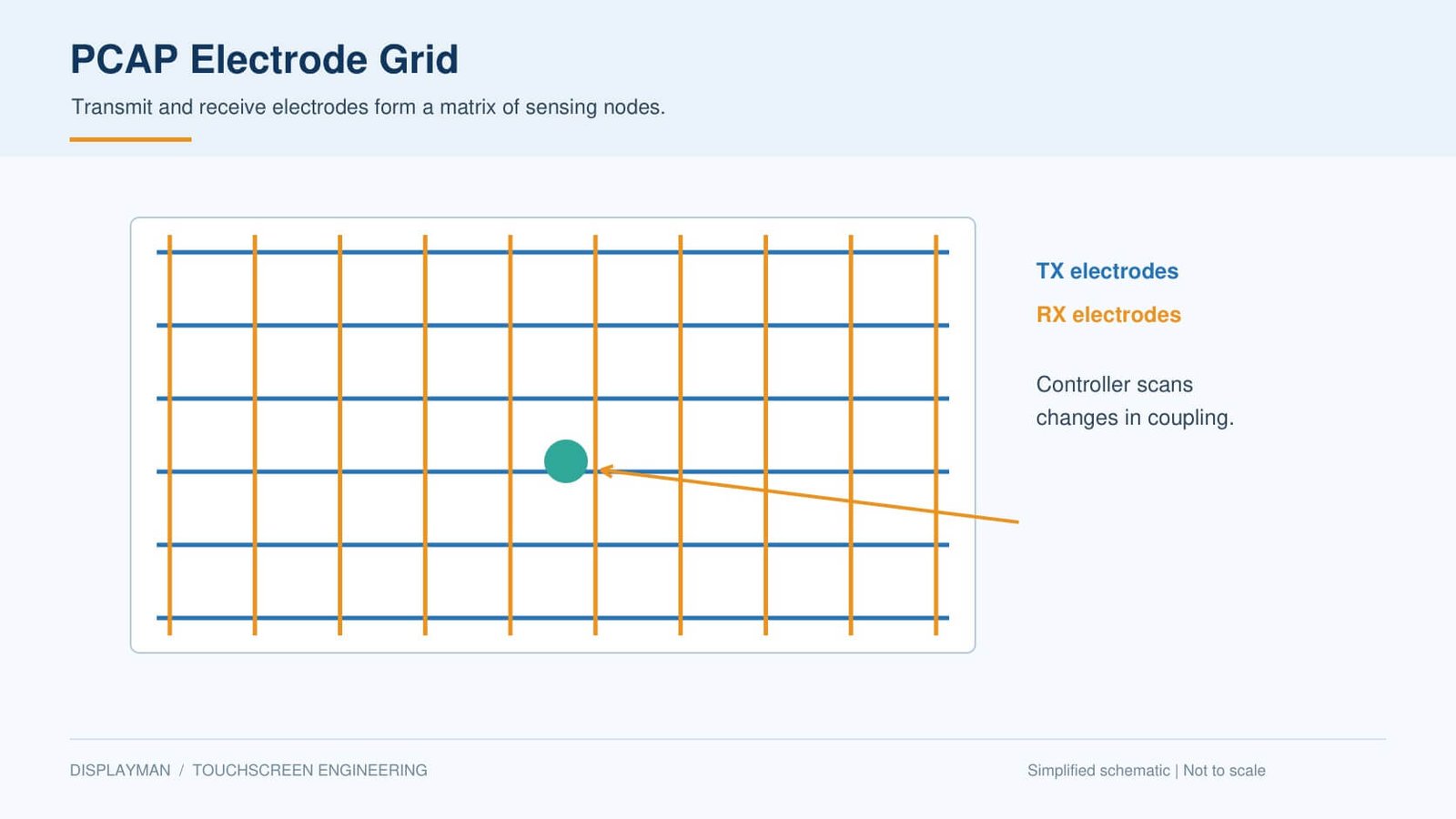
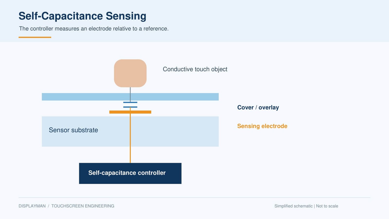
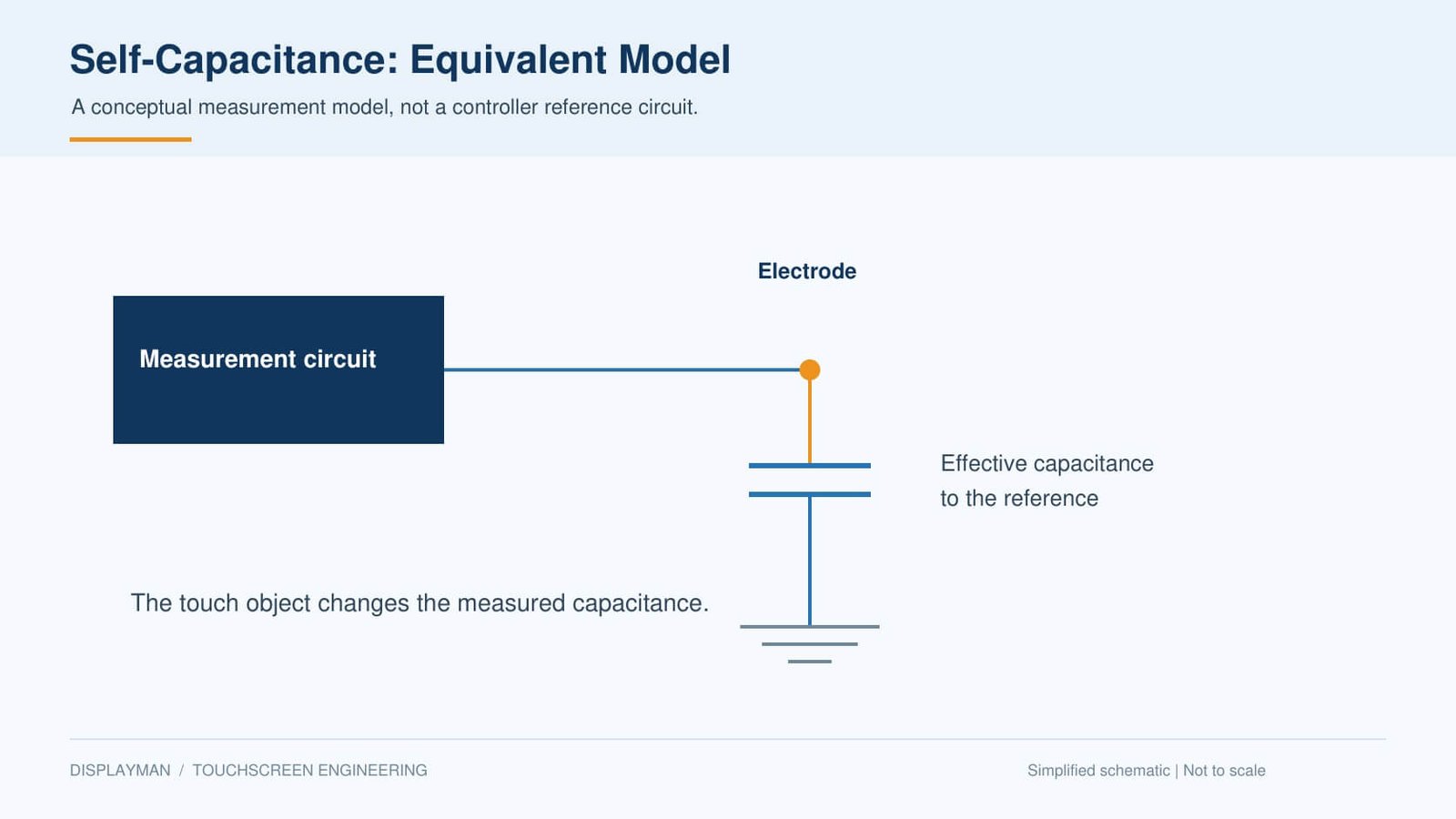
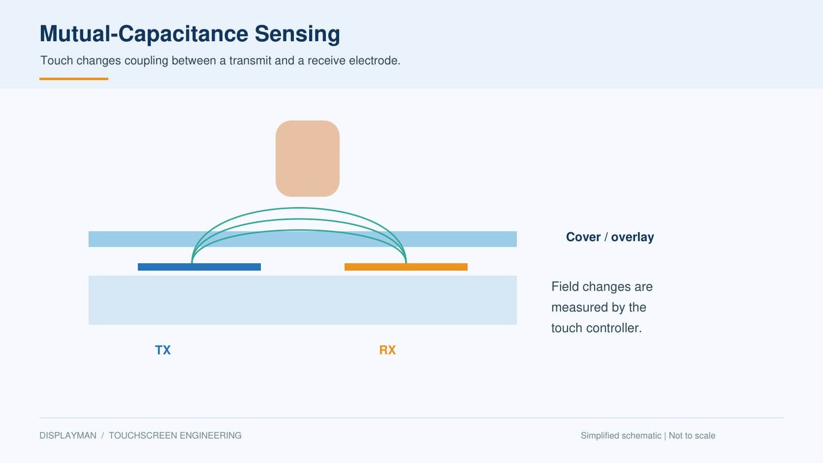
PCAP detects changes in an electric field around a patterned electrode array. A controller measures capacitance changes and calculates touch coordinates. Mutual-capacitance systems measure coupling between transmitting and receiving electrodes; self-capacitance systems measure electrodes relative to a reference. Some controllers combine sensing methods.
The sensing electrodes may be on glass, film or integrated with the display. Common overlay descriptions include G+G, G+F and G+F+F. OGS, On-Cell and In-Cell describe other integration choices, rather than a universal four-layer construction.
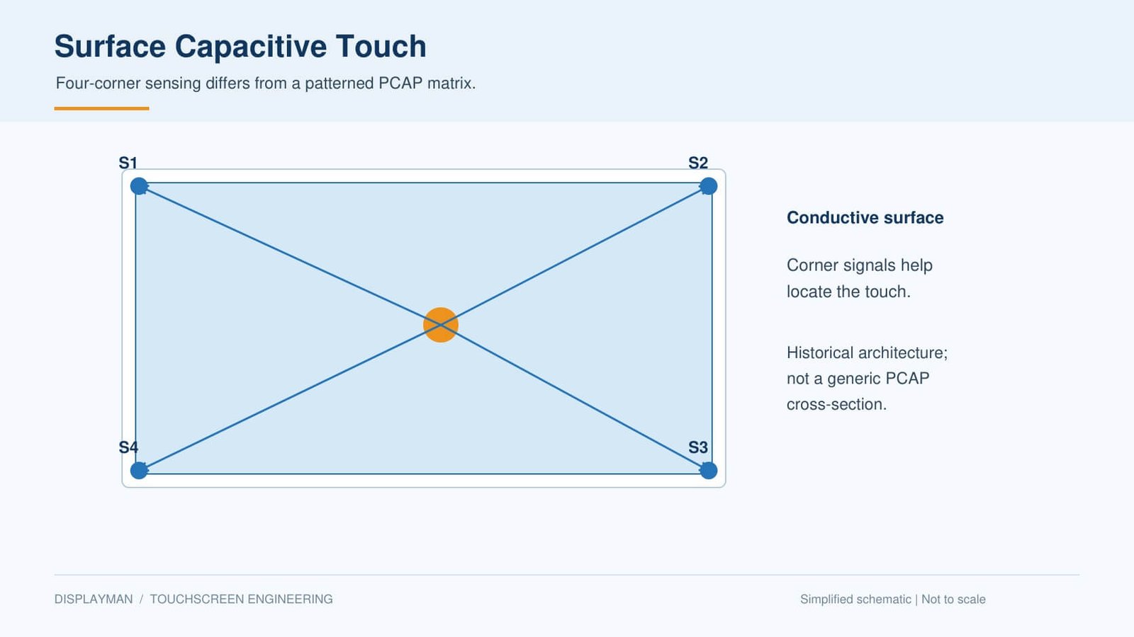
PCAP is different from surface capacitive touch
Older surface capacitive systems can locate a touch by comparing signals at corner electrodes. That description should not be used as the general explanation for a modern PCAP matrix. Sensor geometry, control algorithms and host reporting determine the supported inputs.
For stack choices, cover glass and tuning, see PCAP Touchscreen Customization & Tuning. For integration positions, see OGS vs On-Cell vs In-Cell.
3. How Resistive Touchscreens Work
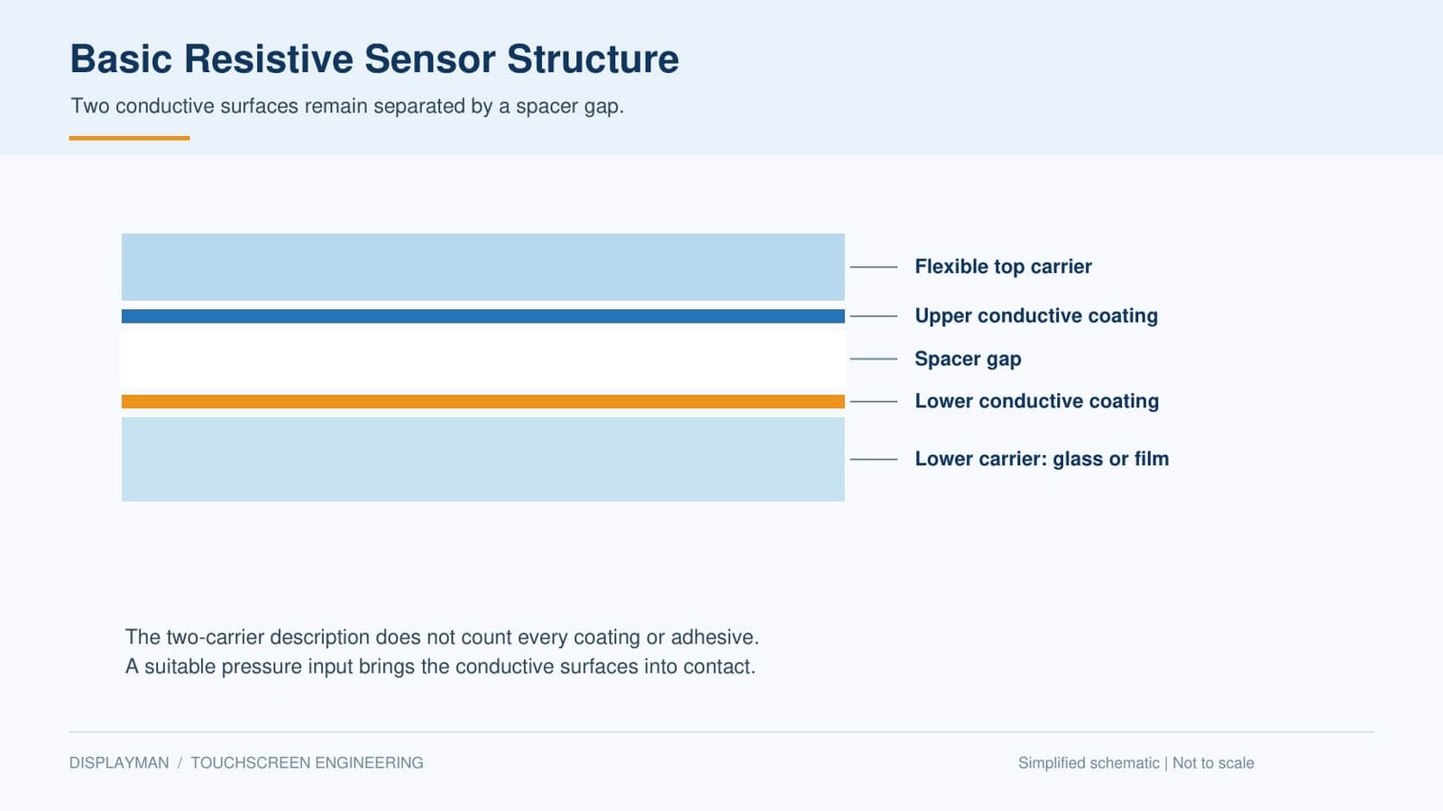
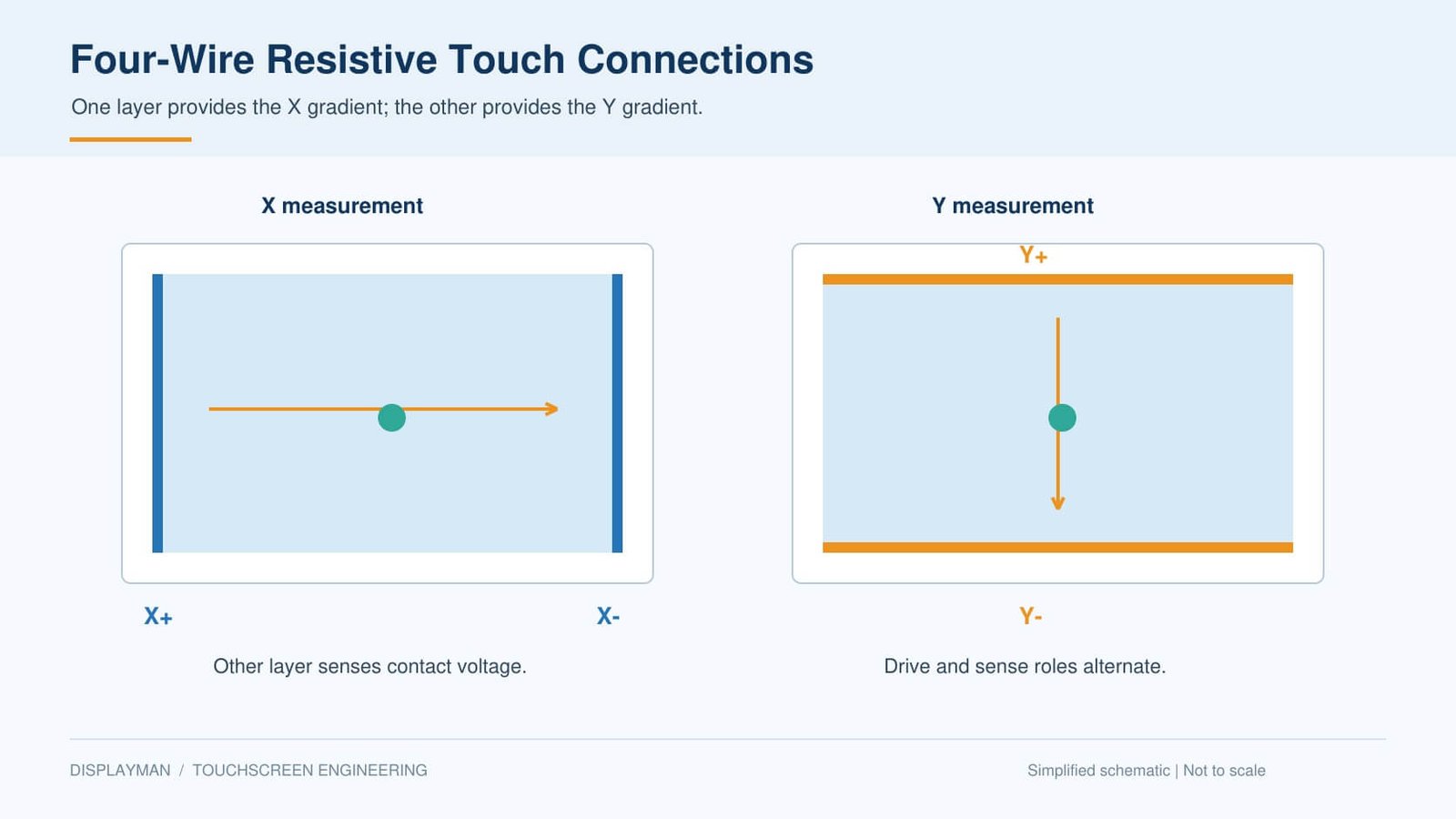
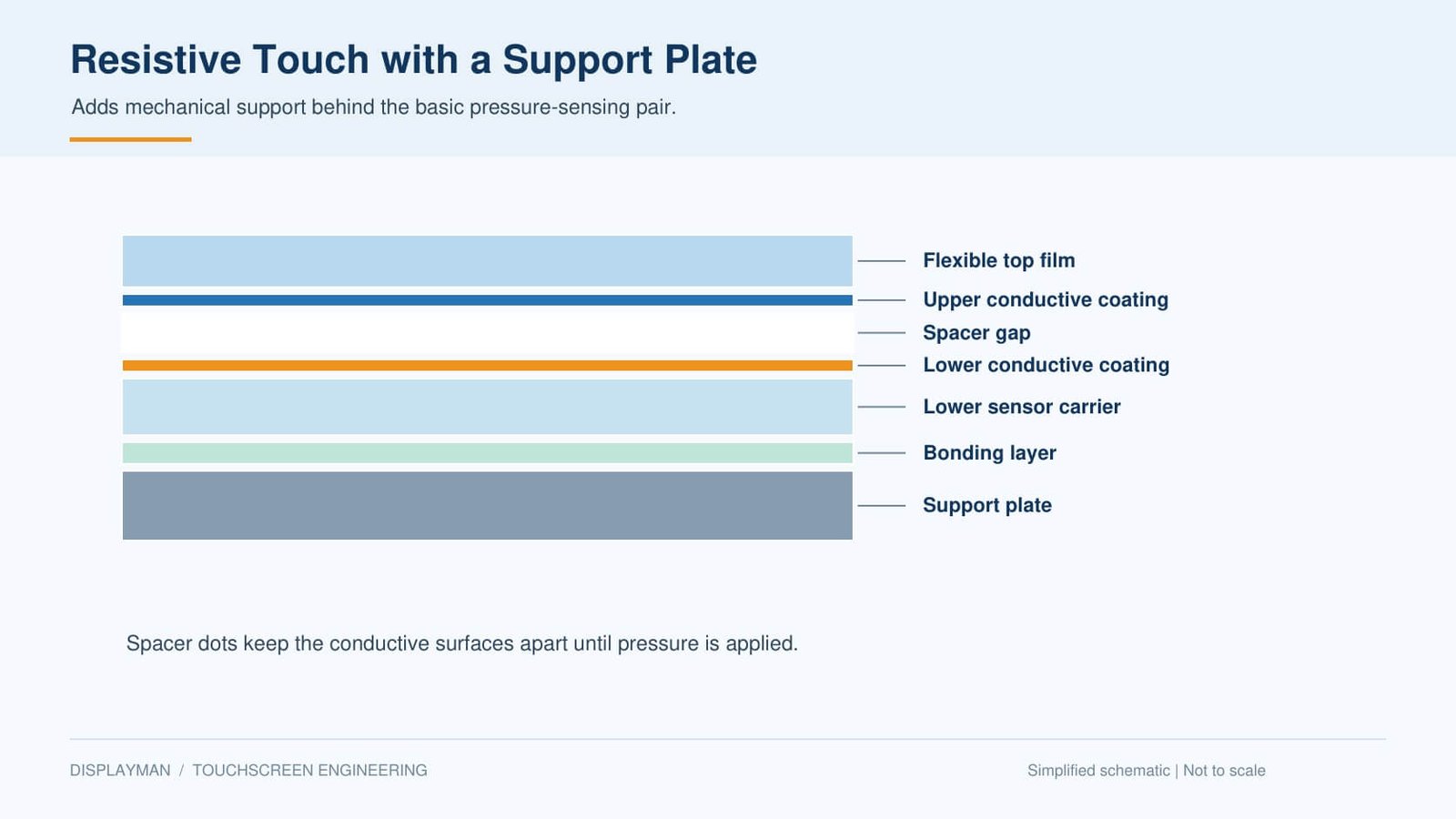
Analog resistive touch uses pressure to bring two separated conductive surfaces into contact. A typical construction has a flexible top layer, a stable lower substrate and spacer dots between conductive coatings. The controller applies a voltage gradient and measures the contact position.
The sensor responds to suitable mechanical pressure, so it can be operated with a finger, many gloves or a blunt passive stylus without needing the same capacitive coupling as PCAP. A sharp tool is not an acceptable input device: it can puncture or damage the surface.
ITO (indium tin oxide) is a common transparent conductive material. Coating composition and layer construction vary; neither every resistive panel nor every capacitive panel uses an identical material stack.
Touch coordinates are not display pixels
A controller’s coordinate range, such as a 12-bit output range, does not establish physical accuracy or guarantee selection of one display pixel. Linearity, noise, calibration, input tool, mounting and software mapping all affect the result.
4. 4-Wire vs 5-Wire Resistive Touch
| Design point | 4-wire resistive | 5-wire resistive |
|---|---|---|
| Coordinate measurement | The two conductive layers alternate drive and sense roles for the two axes. | The stable resistive layer generates both axis gradients; the top layer senses the contact voltage. |
| Connections | Four sensor connections, with supplier-specific pin order. | Four connections to the resistive layer and one sense connection; confirm pinout. |
| Wear considerations | Changes to a conductive layer can affect coordinate measurement. | Separating the sensing role can offer durability benefits in suitable designs; surface damage still matters. |
| Controller selection | Use a controller specified for the sensor and host. | Requires explicit 5-wire support; not a drop-in connection to any 4-wire controller. |
| Quotation | Compare size, force, optical finish and tested life. | Compare the same scope and test conditions; no universal cost or lifetime multiplier. |
Drive voltage is set by the selected controller and sensor specifications. Both layers are not simply held at a fixed 5 V. Calibration and coordinate mapping must be checked on the actual assembly.
5. Capacitive vs Resistive: Practical Comparison
| Selection factor | Projected capacitive (PCAP) | Conventional analog resistive |
|---|---|---|
| Activation | Capacitance change; normally no intentional pressing force. | Pressure brings conductive layers into contact. |
| Finger operation | Well suited to light finger interaction with a matched controller. | Requires sufficient force within the specified range. |
| Gloves | Possible on supported designs; glove material, thickness and tuning matter. | Often a practical option; confirm force and actual glove behavior. |
| Stylus | Compatible passive conductive or supported active pen; not any plastic stylus. | Blunt passive stylus can provide deliberate input. |
| Multi-touch | Commonly supported; touch count and gestures depend on the system. | Common 4-/5-wire analog designs normally report one position. Specialized alternatives exist. |
| Front surface | Often a glass cover with available appearance and surface-treatment options. | Typically a flexible top surface; construction and protective options vary. |
| Optics | Evaluate cover, electrodes, adhesives, coatings and reflection. | Evaluate film, conductive layers, internal gap, finish and reflection. |
| Noise and drift | Check grounding, display noise, power supply and environmental compensation. | Check electrical noise, calibration, mechanical stress and wear. |
| Maintenance | Check cleaning chemistry, impact risk and replacement scope. | Check surface wear, operating force, cleaning and calibration policy. |
| Cost | Depends on size, cover, controller, tooling and quantity. | Depends on sensor construction, controller, durability requirements and quantity. |
Fixed claims such as a universal transmission percentage, response time, number of touches or 30-year life are not reliable technology-wide specifications. Request model data with stated test methods.
6. Advantages and Limits of Each Technology
Why choose PCAP?
- Light finger input and multi-touch can support familiar gesture-based interfaces.
- A glass front can provide a clean appearance and suitable surface treatment options.
- No repeated mechanical contact between sensor layers is required for ordinary touch detection.
These benefits still require the correct controller, sensor and final assembly. Glove support, wet operation, thick glass and electrical noise must be considered together. Higher sensitivity can also make unwanted-input rejection more demanding.
Why choose resistive?
- Pressure input suits many passive stylus and gloved workflows.
- It can be appropriate for established single-touch HMI designs and legacy replacements.
- A defined activation force can be useful where deliberate input is preferred.
The flexible surface has mechanical wear limits. Scratches, repeated loading, unsuitable chemicals and incorrect bezel pressure can damage operation. A 5-wire construction is not permission to continue using a punctured or electrically damaged panel.
7. Gloves, Water, Dust and Electrical Noise
Specify the real conditions rather than asking only for “industrial touch.” A thin disposable glove, leather glove and insulated winter glove are different inputs. Water droplets, a wet finger and a continuous conductive film are also different tests.
PCAP platforms can support gloves and liquid-handling functions, but water rejection and operation while wet are different requirements. Confirm required behavior and false-touch limits with the selected cover and firmware.
Resistive sensing can be useful with contamination or gloves, but a sealed sensor is not the same as a waterproof terminal. Moisture ingress, edge seals, tail exits and enclosure design still need review.
Neither technology is free from all interference. Use the actual power supply, display drive, cables, grounding and enclosure during evaluation. Include electrical disturbances relevant to the equipment rather than relying on a bare sensor test.
8. Optics, Cleaning and Service Life
Outdoor readability depends on display output, reflections, optical bonding, cover finish, content and the installation environment. Capacitive sensing does not make a screen readable outdoors simply because its materials absorb light.
PCAP can be assembled with optical bonding or an engineered air gap. Full optical bonding is not mandatory for every capacitive touchscreen. Resistive constructions have their own optical and mounting limits; obtain an approved assembly method.
Compare cleaning agents, abrasion resistance, impact requirements and service access. Touch-cycle ratings only apply under the specified tip, load and test pattern; they are not the expected life of the whole device.
For optical interfaces, see Optical Bonding vs Air Gap. For reflection, glare and fingerprint treatment, see AR, AG and AF Cover Glass.
9. Choose for the OEM Application
| Application need | Starting point | Approve before selection |
|---|---|---|
| Multi-touch kiosk or modern control UI | Evaluate PCAP. | Touch count, gestures, OS support and public-use durability. |
| Passive plastic stylus with single-touch input | Evaluate resistive. | Tip shape, activation force, mapping and surface life. |
| Gloved industrial HMI | Compare both. | Actual gloves, liquids, noise, target size and operator workflow. |
| Outdoor terminal | Select at complete-system level. | Optics, thermal design, seals, condensation and touch behavior. |
| Legacy resistive replacement | Check a compatible resistive assembly first. | 4-/5-wire type, tail, connector, mapping and mechanical fit. |
Infrared frames and surface acoustic wave systems also exist. Infrared uses an optical beam grid and needs clear optical paths; surface acoustic wave designs use waves across the sensing surface and require contamination assessment. Neither should be ranked by fixed generic response or lifetime figures. For large-format projects, compare the complete implementation.
10. Interfaces, Calibration and Sample Approval
A bare resistive sensor tail is not a USB interface. A controller converts sensor measurements into host input. PCAP can also require a dedicated controller, with host connections such as I²C or USB depending on the design. Check logic levels, pinout, firmware and operating-system support.
Changing from resistive to PCAP is not generally a sensor-only swap. Review cover dimensions, mounting, driver support, touch mapping, power and UI behavior. Handwriting recognition is largely a host/software function and compatible-input question, not an inherent exclusive feature of either technology.
- Map coordinates: check edges, corners, rotation and the actual UI target sizes.
- Test inputs: use the required fingers, gloves, stylus and gestures.
- Verify disturbances: check liquids, display content, power changes and noise under defined conditions.
- Inspect optics and mechanics: evaluate reflection, mounting pressure, seals and tail strain.
- Record configuration: approve sensor, controller, firmware, host driver and assembly revisions together.
PCAP commonly uses baseline compensation, whereas resistive systems may need coordinate calibration. Neither supports an unconditional promise of “never drift” or “routine recalibration always required.” Define the actual acceptance and maintenance procedure.
11. Self-Capacitance and Mutual Capacitance
The capacitive training deck distinguishes two measurement approaches. Self-capacitance measures an electrode relative to a reference; mutual capacitance measures coupling between transmitting and receiving electrodes. These are sensing methods, not descriptions of whether the touch carrier is glass or film.
| Design question | Self-capacitance | Mutual capacitance |
|---|---|---|
| What is measured? | The capacitance associated with an electrode relative to its reference. | The coupling capacitance between a driven electrode and a receiving electrode. |
| Matrix interpretation | Simple row/column implementations can have ambiguous combinations when multiple touches occur. | Scanning intersections can distinguish simultaneous touch positions. |
| Data model | A simple row/column example measures roughly M + N electrode signals. | A full M-by-N intersection scan contains roughly M × N sensing nodes. |
| Useful capabilities | Can support sensitive detection and proximity-related functions in suitable systems. | Often used for multi-touch position tracking. |
| What cannot be inferred? | No universal six-inch size ceiling, speed limit or fixed accuracy applies to the whole method. | No universal ten-touch limit, noise immunity or power consumption applies to the whole method. |
Consider two touches on different rows and columns. Independent row and column signals can describe four possible intersections, creating the classic ghost-point ambiguity in a simple self-capacitance matrix. Controller design and sensing strategy determine how a real product addresses this problem. Modern systems may combine sensing approaches.
The source deck’s simple complexity comparison helps explain why channel count matters. It does not directly establish processor speed, frame rate or energy use, because controllers use different scan schedules and signal-processing methods.
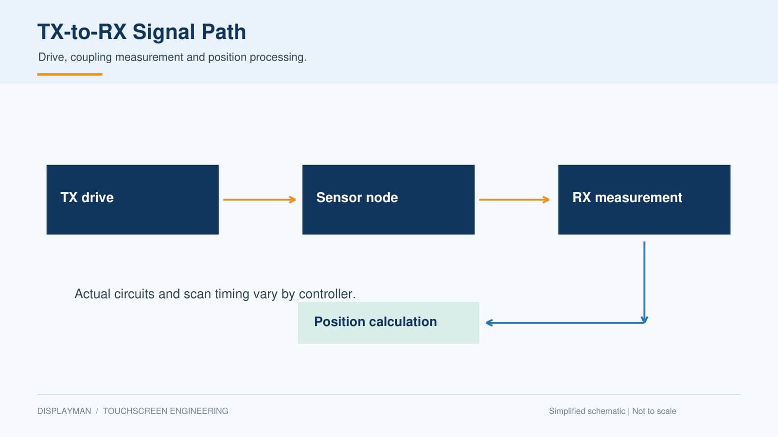
12. PCAP Stack Structures: G+G, G+F, G+F+F, SITO and DITO
The source’s structure tables become more useful when read as a map of manufacturing choices rather than a universal ranking. Cover material, sensor carrier, electrode layout and controller must be specified separately.
| Term | Basic meaning in this guide | Engineering implications |
|---|---|---|
| G+G | Glass cover plus a separate glass sensor. | Review total thickness, edge protection, glass strength and adhesive layers. |
| G+F | Glass cover plus one film sensor carrier. | Confirm how transmitting and receiving electrodes are implemented; the name alone does not establish touch count. |
| G+F+F | Glass cover plus two film sensor carriers. | Review film handling, lamination, optical interfaces and dimensional stability. |
| G+G with SITO | A glass sensor with its sensing pattern formed on one side in the supplier’s described process. | Electrode crossings can require bridges and insulation. Ask for the actual cross-section. |
| G+G with DITO | A glass sensor with conductive patterns on two sides in the described process. | Review protection of each side, routing, lamination and electrical connection. |
| OGS | Touch sensing integrated into the cover lens. | Cover geometry, strengthening and sensor processing become linked manufacturing decisions. |
Single-side patterns may use an insulating crossing structure and an ITO or metal bridge. The deck discusses resistance, visible patterning, protection and ESD trade-offs for its particular processes. Those trade-offs should prompt a design review, not a blanket statement that one architecture always has superior ESD performance or environmental reliability.
A structure label also cannot establish freedom from patent restrictions. Current legal clearance requires a separate assessment of the actual product and process.
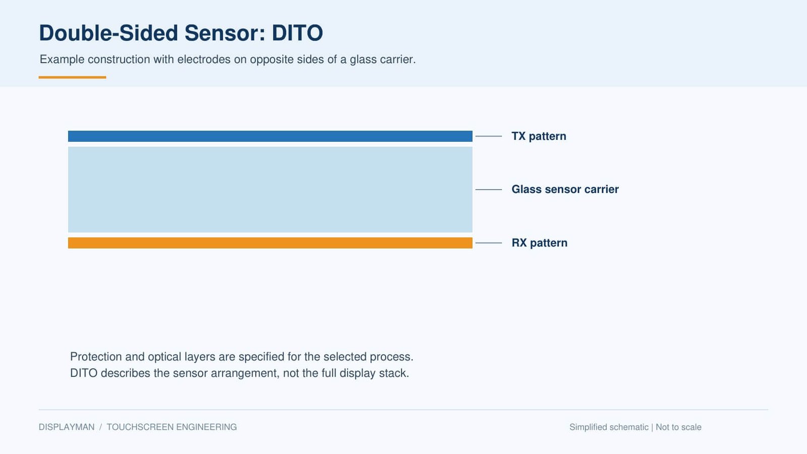
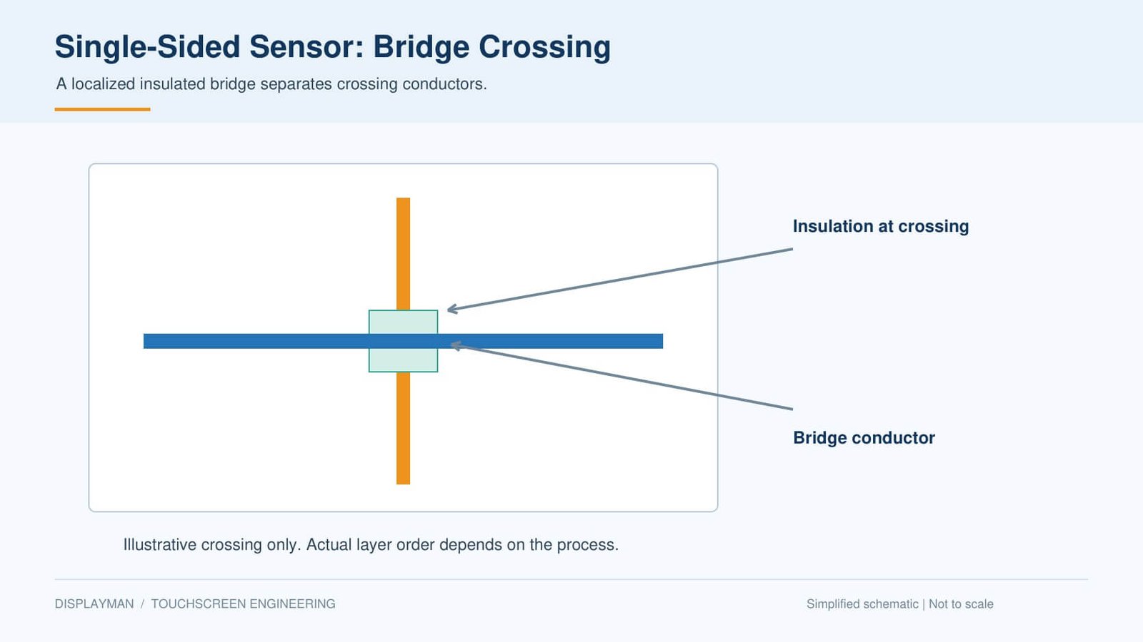
13. Cover Glass, Sensor Glass and Film Materials
Cover thickness and strengthening
The capacitive deck lists cover thickness examples from 0.55 mm to 5.0 mm, including 0.7, 1.0, 1.1, 1.8, 2.0, 3.0 and 4.0 mm. These are historical manufacturing examples, not approved limits for every controller. A thicker cover increases the sensing distance and changes the signal budget. Air gaps, decoration, glove thickness and sensor geometry also contribute.
For chemically strengthened glass, surface compressive stress (CS) and depth of layer (DOL) help describe the strengthening condition. They do not independently predict finished-product drop resistance. Glass composition, edge finishing, holes, printing, mounting and defects remain important. The deck’s old brand-level CS/DOL table should not substitute for a current glass-grade specification.
Sensor carrier examples from the training material
| Material | Examples recorded in the source | What to approve |
|---|---|---|
| PCAP sensor glass | 0.4, 0.55, 0.7, 1.1 and 1.8 mm | Handling strength, flatness, edge support, strengthening and optical quality. |
| PCAP sensor film | 0.05, 0.075, 0.10 and 0.125 mm | Wrinkling, creasing, dimensional stability and the approved lamination process. |
| Resistive ITO glass | 0.7, 1.1 and 1.8 mm common in the deck; 0.55 and 2.8 mm also listed. | Mechanical fit, electrode coating, optical transmission and controller compatibility. |
| Resistive decorative front sheet | 0.125, 0.188 and 0.25 mm | Required operating force, flatness and surface finish on the actual construction. |
These dimensions describe individual materials, not finished module thickness. Ask whether a quoted dimension includes coatings, printed decoration, adhesive and tolerances. Avoid transferring a source’s size-versus-thickness recommendation into a universal glass design rule.
AR, AG and AF serve different purposes
AR addresses reflection, AG spreads reflected light to reduce glare, and AF helps control fingerprint adhesion and cleaning. The source lists several coating and etching processes, but durability and optical effects depend on the actual treatment. Specify reflection, haze, image clarity and cleaning performance rather than choosing by a process name alone.
14. ITO Sheet Resistance, Electrode Visibility and Optical Adhesives
Sheet resistance uses Ω/□, or ohms per square. It differs from the measured resistance of an entire trace, which also depends on geometry and interconnection. The capacitive deck lists sensor-glass coating ranges spanning approximately 40–600 Ω/□ and film examples of 100 ± 50 and 150 ± 50 Ω/□. These values belong to its historical material options.
Lower sheet resistance can help reduce electrical settling time in a suitable electrode design. Optical transmission, pattern visibility, coating properties and cost must also be considered. Do not infer that every low-resistance coating is visibly worse or that a particular resistance always removes the need for optical pattern treatment.
Pattern visibility can appear as electrode outlines, reflective traces or texture under particular lighting. Inspect the final display at different backgrounds and angles. A transparent material sample alone will not establish the appearance after bonding.
OCA film and liquid optical adhesives
The deck uses “liquid OCA” for a liquid adhesive option. In this guide, OCA refers to optically clear adhesive film; LOCA identifies liquid optically clear adhesive. Cure method and rework behavior must be specified for the actual chemistry.
| Source example | Recorded thickness | Interpretation for a new design |
|---|---|---|
| Film-to-film OCA | 0.025 or 0.050 mm | Historical internal sensor-lamination examples. |
| Film-to-glass OCA | 0.075, 0.100 or 0.125 mm | Review step coverage, bubbles and the exact film/glass combination. |
| UV-process adhesive examples | 0.20 or 0.30 mm before the source’s stated cure step | Final bondline depends on chemistry and process. Do not apply the deck’s cure-thickness reduction to other adhesives. |
Approve the adhesive’s optical properties, yellowing, compatibility with polarizers and printing, environmental behavior, cure conditions and repair process. Fewer layers can simplify assembly, but manufacturing loss depends on which components become inseparable and how defects are detected.
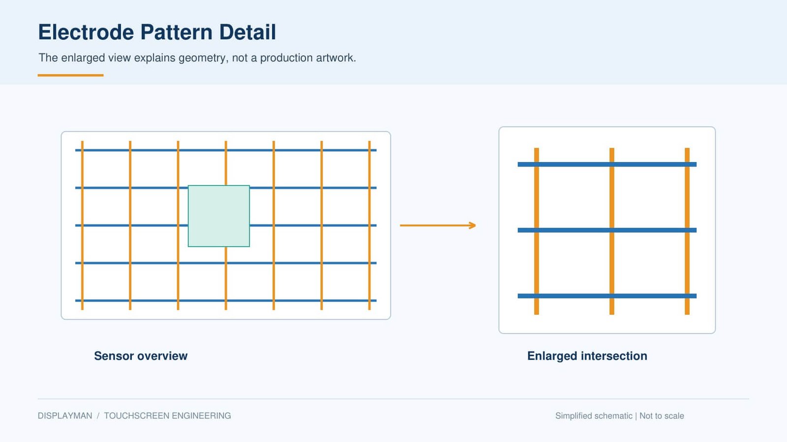
15. Resistive Two-, Three- and Four-Layer Constructions
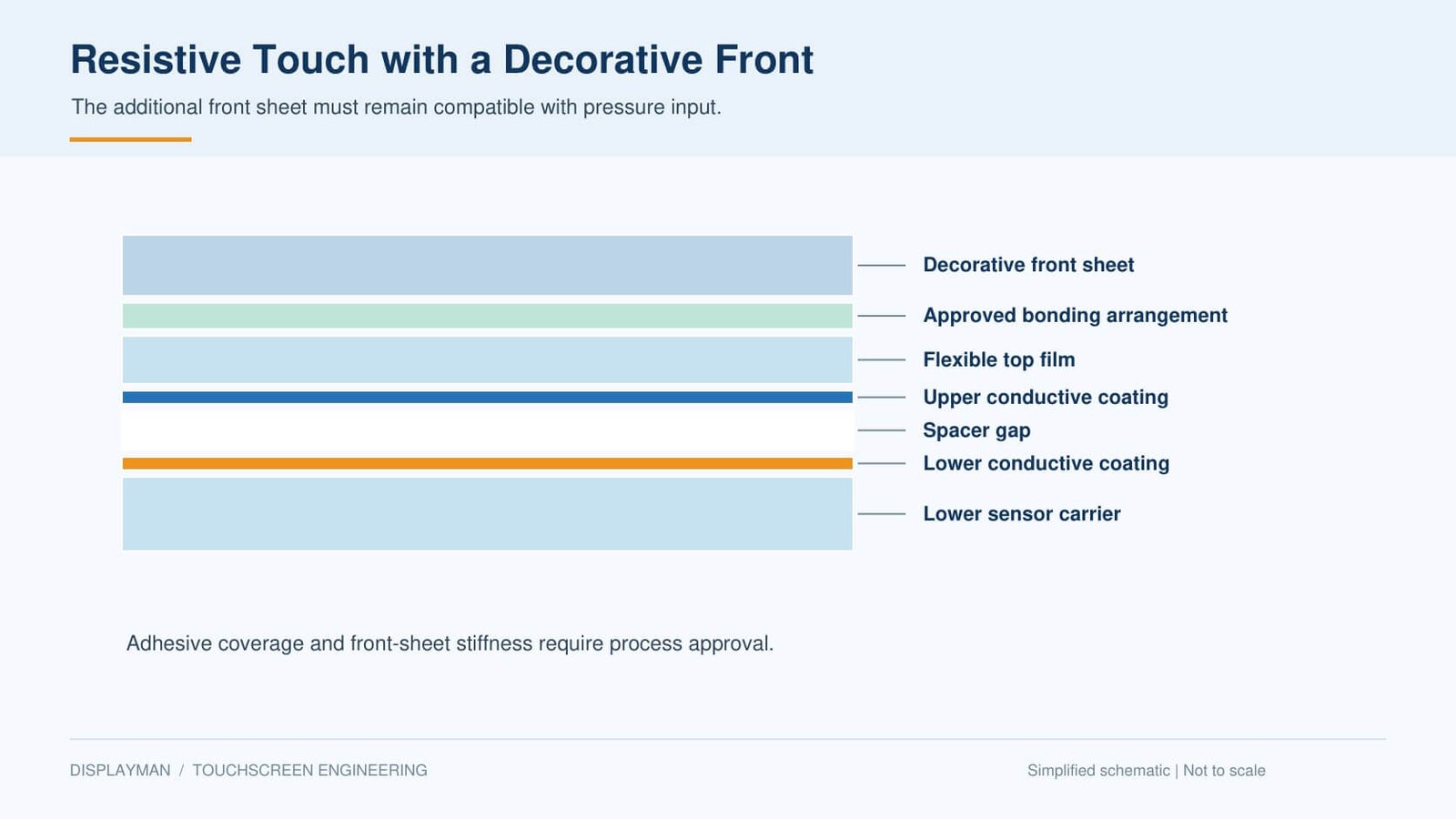
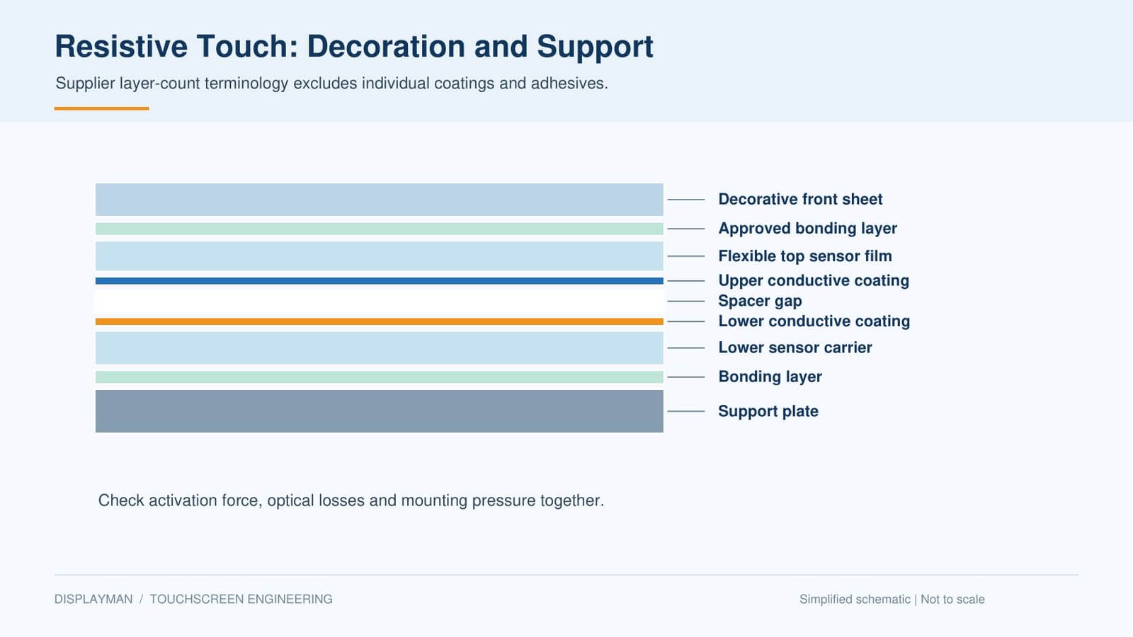
The resistive deck distinguishes the sensing pair from added appearance and support layers. This is useful when a customer wants a clean front face without losing pressure sensitivity.
| Source construction | What is added? | Selection trade-off |
|---|---|---|
| Basic two-layer sensing construction | A flexible conductive top carrier and a second conductive carrier, separated by spacers. | Provides the pressure-contact mechanism. The lower carrier may be glass or film, depending on design. |
| Three-layer with decoration | A decorative front sheet above the sensing construction. | Can improve the product face, but additional compliance and thickness affect force and optics. |
| Three-layer with support | A support plate behind the sensing construction. | Improves mechanical support subject to material, thickness and mounting. |
| Four-layer construction | Both decoration and support. | Combines appearance and support with more thickness, interfaces and process steps. |
“Two-layer” here is a supplier construction description, not a count of every coating, spacer and adhesive. Ask for a complete sectional drawing before comparing quotes.
Operating force and edge wear
The source identifies repeated stylus movement near the boundary of the active field as a potential wear mechanism in a 4-wire panel. Local bending and shear can damage the conductive film. Test frequently used UI controls and edge-drawing paths with a defined tip and force.
Check bezel clearance, gasket load and adhesive position. Constant pressure at the perimeter can create unintended contact or distort behavior. An attractive flush front requires an approved mechanical construction; it cannot simply clamp an arbitrary resistive film beneath rigid glass.
16. Resistive Surface Finishes, Support Plates and Additional Wire Types
Film and decorative surface choices
The source discusses glossy hard-coated film, anti-Newton-ring treatment and matte anti-glare options. Glossy surfaces can preserve clarity but show reflections; a matte treatment changes glare and haze. Anti-Newton-ring treatment addresses interference fringes from close optical surfaces. These are different requirements and should have separate acceptance criteria.
Increasing a front sheet’s thickness can increase operating force in a given design, but the full construction determines the result. Verify activation force across the whole active area rather than only at its center.
Support material selection
| Material direction | Why consider it? | What needs checking? |
|---|---|---|
| Glass | Flatness and a relatively hard surface. | Edge impact, mounting stress, weight and breakage risk. |
| PC | Impact-tolerant support in an appropriate construction. | Scratching, thermal expansion, optical quality and chemical compatibility. |
| PMMA | Optical and surface characteristics suited to some designs. | Impact performance, deformation, shrinkage and chemical exposure. |
| PC/PMMA composite | Combines material characteristics for a specified purpose. | Actual grade, interfaces, availability and finished-assembly qualification. |
The deck lists glass support examples of 0.55–1.8 mm and polymer/composite examples of 0.5–1.5 mm. Its pencil-hardness figures describe particular materials and tests, not universal impact ratings. Thickness and hardness do not establish the durability of the assembled terminal.
Six-, seven- and eight-wire references
The source also mentions extra shield and sense connections in less common resistive configurations. Additional sense leads can help a compatible controller account for connection resistance, while a separate shield can address coupling from behind the sensor. Naming conventions and pin functions vary. Obtain the supplier drawing and controller specification instead of treating wire count as an automatic upgrade path.
17. FPC, Connector and Touch Controller Selection
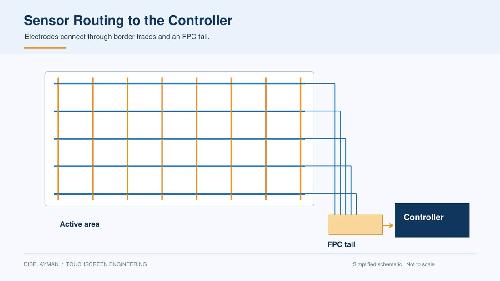
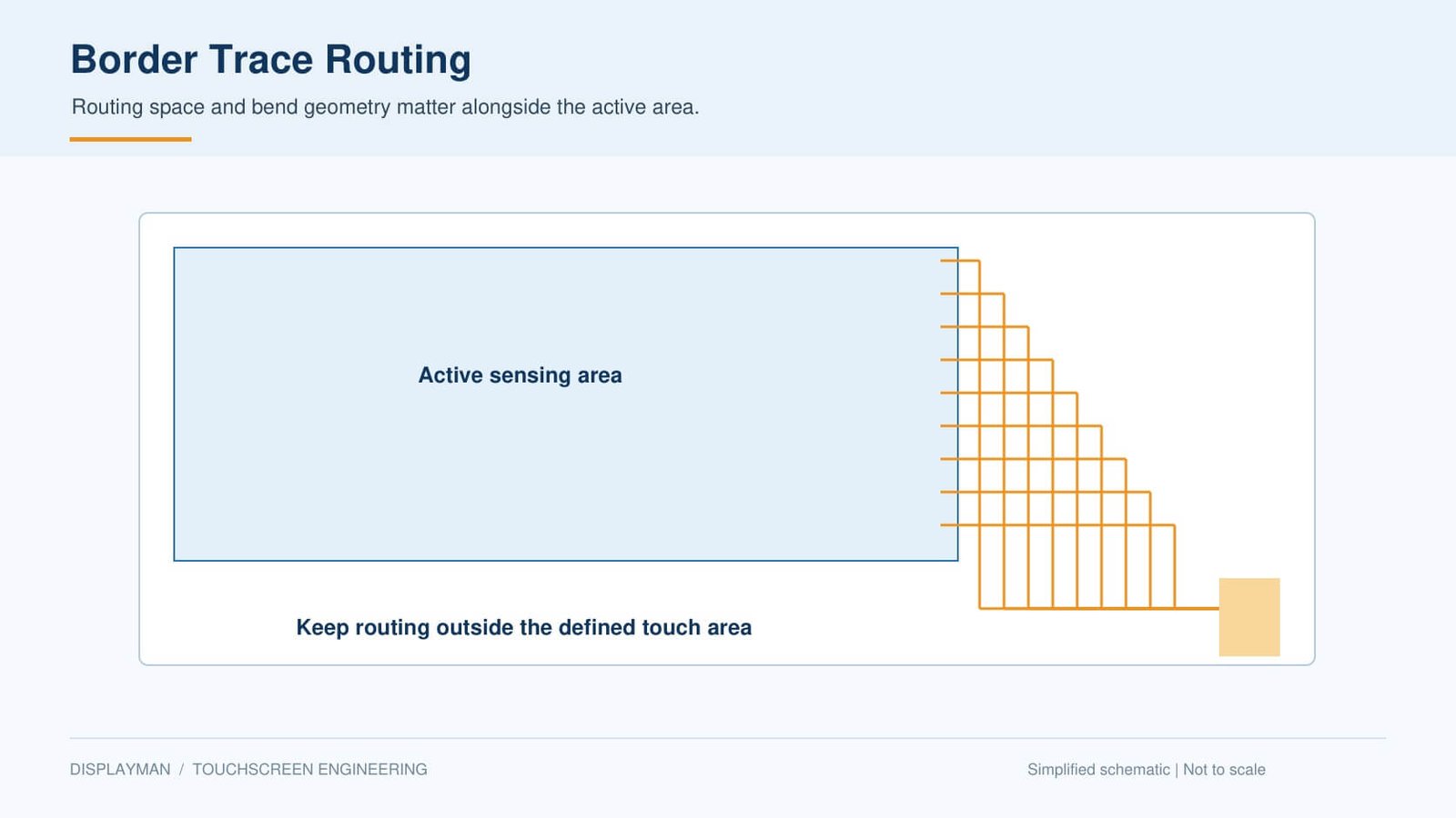
Both presentations make clear that the tail and controller are part of the sensor design. Specify the FPC outline, exit position, copper routing, connector pitch, contact side, stiffener and bending clearance. A physical connector match does not guarantee an electrical match.
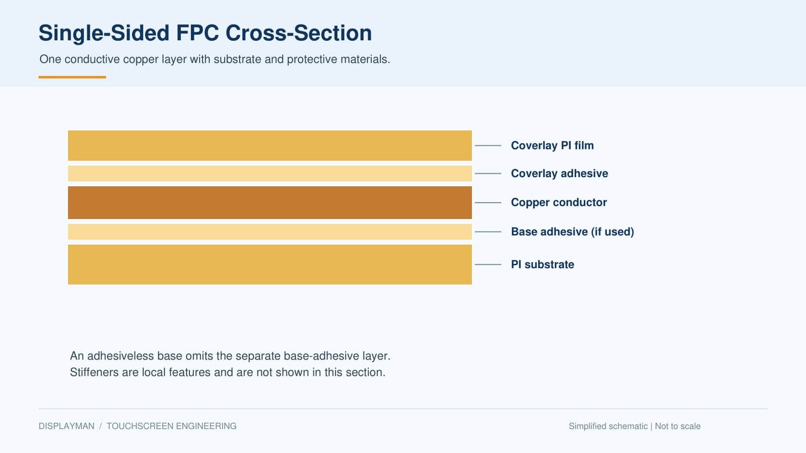
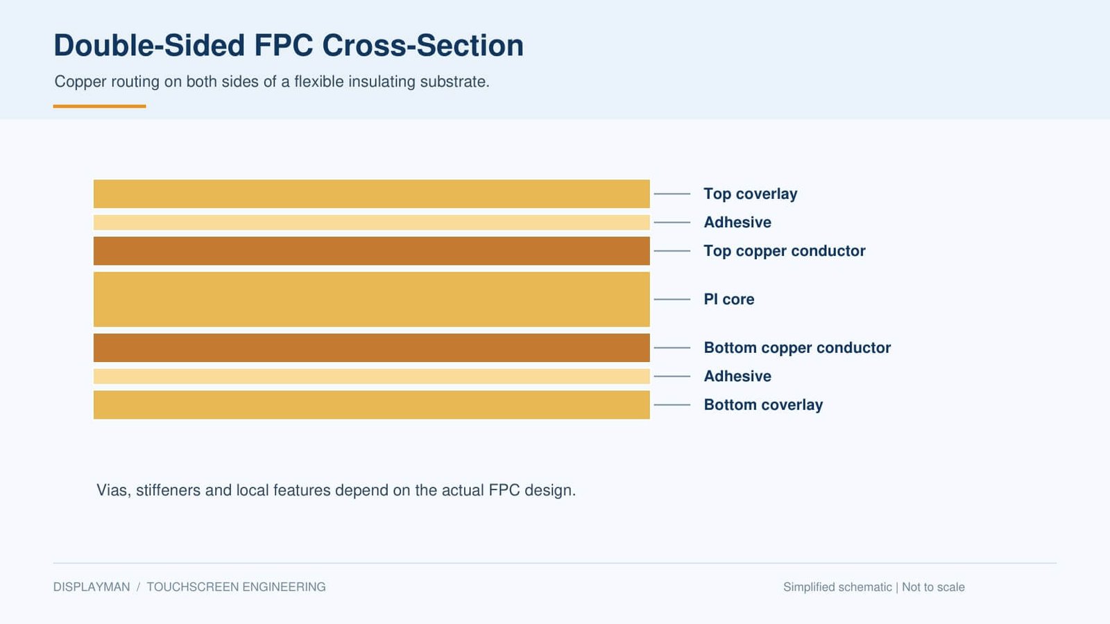
FPC materials can include PI substrate, copper foil, coverlay, adhesive and local reinforcement. Adhesiveless construction, copper type and layer count affect manufacturing and bending behavior. PI, FR4 and steel stiffeners serve different connector and support needs; none is universally the right choice for all resistive or capacitive panels.
Keep bending away from bonded connections, stiffener transitions and components unless the approved design explicitly allows it. Separate a one-time installation bend from repeated dynamic flexing. For related integration, see FPC and Cable Assembly.
Replace a legacy IC list with a controller approval matrix
| Controller criterion | Evidence to request |
|---|---|
| Sensor drive and channels | Compatibility with actual Tx/Rx count, electrode dimensions, resistance and capacitance. |
| Input capabilities | Required touch count, glove, water behavior and supported pen tested on the final cover. |
| Host connection | USB, I²C, SPI or other supported interface, voltage levels, pinout and driver requirements. |
| Noise behavior | Evaluation with display drive, charger or power supply, grounding and final cable lengths. |
| Firmware control | Configuration version, tuning support, update method and production lock procedure. |
| Supply support | Current lifecycle, lead time, approved alternatives and long-term support arrangements. |
The 2017 capacitive deck lists devices from Synaptics, Elan, EETI, Pixcir, Chipone, Goodix, FocalTech and MStar. Those names explain its historical platform coverage. The old model tables, stock figures, support ratings and replacement suggestions are not current purchasing recommendations. Verify the exact IC and firmware before approving a new design.
18. Manufacturing Review and Qualification Plan
Use the source material as a checklist for the supplier discussion. An electrode pattern, adhesive or glass change may affect touch behavior even when the external outline stays the same.
- Freeze the stack: approve cover and carrier materials, thicknesses, printing, adhesive and sensor position.
- Review sensor processing: check pattern definition, bridges, insulation, trace protection and connection quality.
- Approve lamination: inspect alignment, particles, bubbles, bondline coverage and optical appearance using agreed lighting.
- Approve mechanical assembly: check bezel pressure, edge clearance, support, flex routing and strain relief.
- Tune the assembled system: test the actual controller, display, host, cables and power supply.
- Agree qualification: define temperature, humidity, cleaning, ESD, electrical immunity and mechanical tests relevant to the equipment. Record pass/fail criteria and sample conditions.
- Control changes: identify material, sensor, firmware and process revisions on the approved sample record.
For a resistive wear test, state the tip material and radius, force, speed, path, cycle count and allowed change in force or coordinate error. For PCAP, state the input objects, required gestures, unintended-input limits and environmental conditions. This turns an impressive cycle count or touch claim into a test that can be repeated.
A bare panel test does not certify a finished product. Use the equipment’s applicable requirements and agreed test plan to decide what component and system evidence is needed.
19. What to Send Before a Quotation
Send the display size or model, outer dimensions and active area, mounting drawing, expected quantity and host interface. Include the input method, actual gloves or stylus, operating environment and whether multi-touch is required.
For replacements, provide the original sensor specification, 4-/5-wire arrangement where applicable, FPC dimensions, connector and controller details. For custom PCAP, include cover thickness, printing, holes and surface-treatment requirements.
DisplayMan can review a separate touch panel or an integrated touch display assembly. Compare quotations at the same scope: sensor, controller, cover, bonding, tooling, testing and service parts.
20. Frequently Asked Questions
Can capacitive touch work with gloves?
Yes, supported PCAP configurations can. Confirm the exact glove material and thickness with the final cover and tuning.
Can resistive touch support two fingers?
Common analog 4-/5-wire designs are normally single-touch. Specialized resistive multi-touch designs exist; confirm the actual product rather than assuming support.
Which is more accurate?
Neither name defines final accuracy. Compare physical error, repeatability and UI selection using the intended input device, not only digital coordinate counts.
Is capacitive touch always more expensive?
No fixed percentage applies. Size, customization, controller, qualification, quantity and assembly scope determine the quotation.
Do resistive panels need a stylus?
No. A finger or suitable glove can also operate them if the required force is applied. Avoid sharp objects.
Which technology is waterproof?
Waterproofing belongs to the finished assembly and its tested sealing design. Touch behavior under liquid exposure is a separate requirement.
Explore Related Display Products
Choose a touch component, integrated display module or complete terminal according to your project scope.
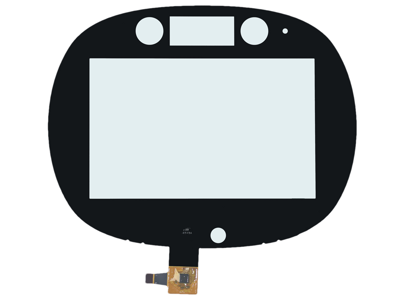
Capacitive Touch Panels
Explore PCAP panels, custom cover glass and matched touch controller options.
Explore product options →
Touch Screen TFT LCD Displays
Select the display and touch assembly together around your host system.
Explore product options →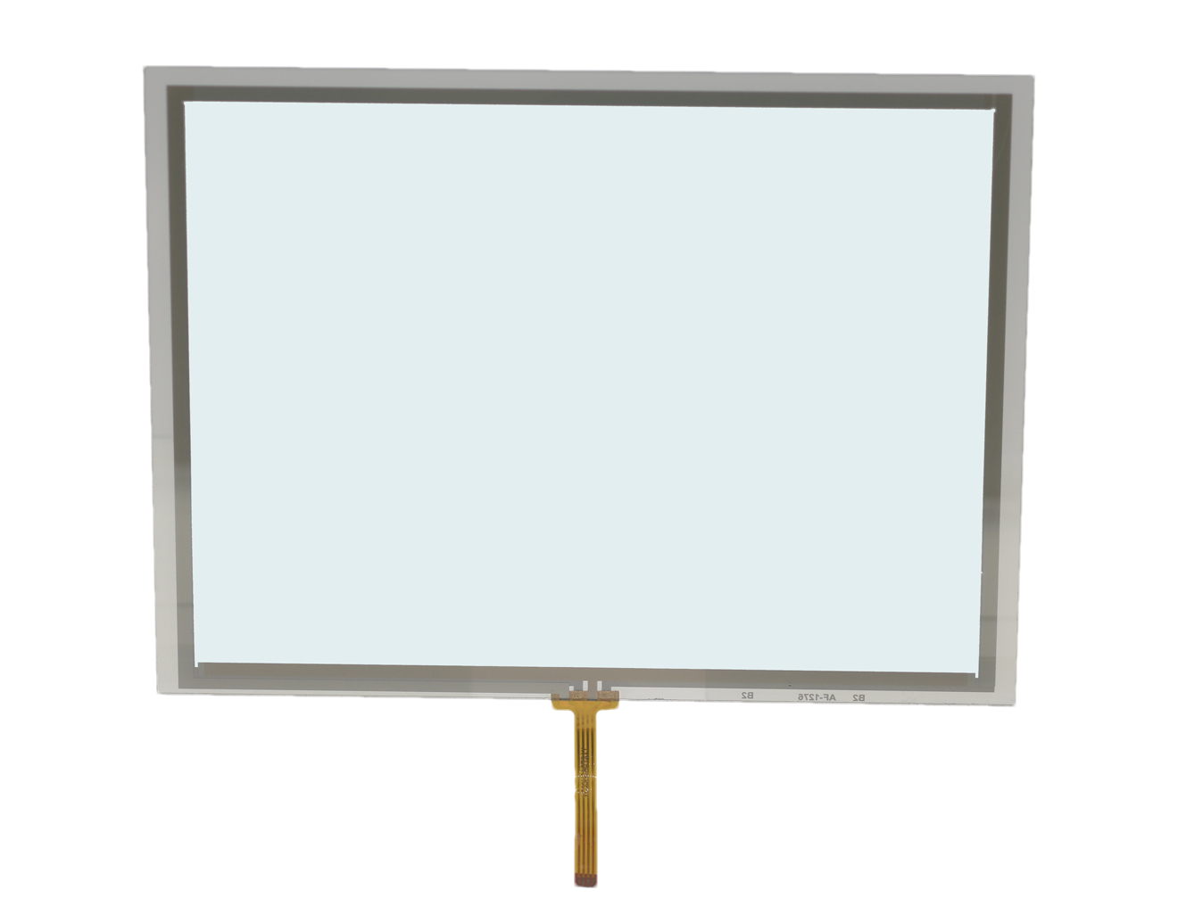
Resistive Touch Panels
Review 4-wire and 5-wire options for pressure input, stylus use and legacy replacement.
Explore product options →Project review
Compare Touch Options for Your OEM Product
Send your display model, touch method, gloves or stylus, operating conditions, host interface and quantity. DisplayMan can review the panel and integration requirements.
Prefer to open the enquiry form here?
Related Guides and Technical References
PCAP customization and tuning · Optical bonding vs air gap · AR, AG and AF cover glass
Microchip AVR341: four- and five-wire resistive touch controllers · Infineon: industrial capacitive touchscreen design
References explain sensing and design principles. They do not establish that every capability is available on a particular DisplayMan configuration.
Supplied Training References
Engineering detail also draws on the supplied capacitive touchscreen training presentation (22 slides) and resistive touchscreen training presentation (18 slides), last saved in 2017. Material dimensions are historical examples, not a current DisplayMan catalogue. Selected definitions and electrical principles have been corrected against controller documentation. Current availability, performance and qualification require the selected product specification.