Greg’s LCD module engineering experience
What Is the Difference Between COB, COG and COF?
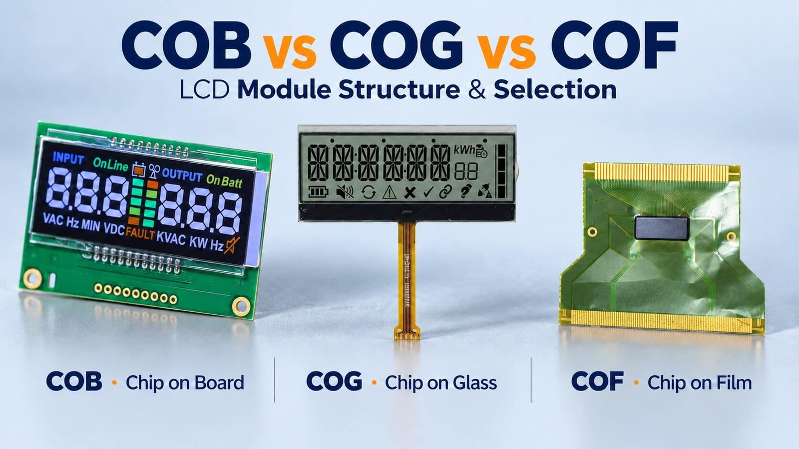
COB mounts the driver chip on a circuit board, COG mounts it on LCD glass, and COF mounts it on a flexible film circuit. The appropriate choice depends on the complete module dimensions, available driver platform, connection, development scope and order quantity.
This DisplayMan comparison preserves my original three product images and the cost lesson behind custom COG development. It also explains why an FPC connection alone does not make a module COF.
What COB, COG and COF Actually Describe
These terms identify where the driver chip is mounted. They do not tell you whether the LCD is positive or negative, segment or dot matrix, transmissive or reflective.
A module may include LCD glass, a driver, a backlight, connections, supporting electronics and mechanical parts. Not every module has a dedicated PCB or a backlight: reflective designs and different integration levels need different assemblies.
| Technology | Full name | Driver-chip location | Integration question |
|---|---|---|---|
| COB | Chip on Board | A circuit board | How do the board, LCD and housing fit together? |
| COG | Chip on Glass | The LCD glass | How are the glass driver, external connection and host electronics integrated? |
| COF | Chip on Film | A flexible film circuit | Is a suitable film-mounted driver platform available for the design? |
Character count and graphic resolution are another classification. Both character and graphic LCD modules can use different driver-mounting arrangements. Choose the content requirement and physical architecture together.
COB: Driver Chip on the Circuit Board
In a typical bare-die COB construction, the chip is attached to the PCB, its pads are wire-bonded to board pads, and the die and fine wires are protected by an encapsulant. The black glob-top visible in the original photograph is protective material over that assembly.
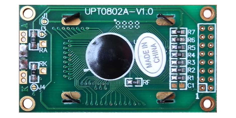
The original description called the encapsulant a sticky piece of plastic and the wire-bond process soldering. The important distinction is that die attachment, wire bonding and encapsulation are separate controlled steps. Bond-wire material depends on the process; aluminum is one possible example rather than a requirement for every module.
The PCB provides space for routing and, where required, support components or connections. The LCD can connect through a conductive rubber strip, pins or another designed arrangement, with the mechanical frame maintaining the intended alignment and contact conditions.
COB remains a useful option for monochrome instruments, character modules and established industrial assemblies. My original view of its strong reliability came from practical projects. It should not be interpreted as proof that every COB product is more reliable than every COG or COF product.
Size and service considerations
A board-based assembly may take more space, but that board can also simplify mounting and external interfacing. Do not count it only as unwanted volume.
Serviceability depends on the failure and construction. A removable contact or cable fault differs from a damaged encapsulated die or broken LCD glass. COB is not automatically indestructible or universally impossible to repair; production replacement is often the practical option for a bonded-chip failure.
COG: Driver Chip on the LCD Glass
In COG, the driver chip is bonded directly to the glass contact region using a suitable bonding process. This can reduce the dedicated board area and interconnect complexity associated with the display driver.
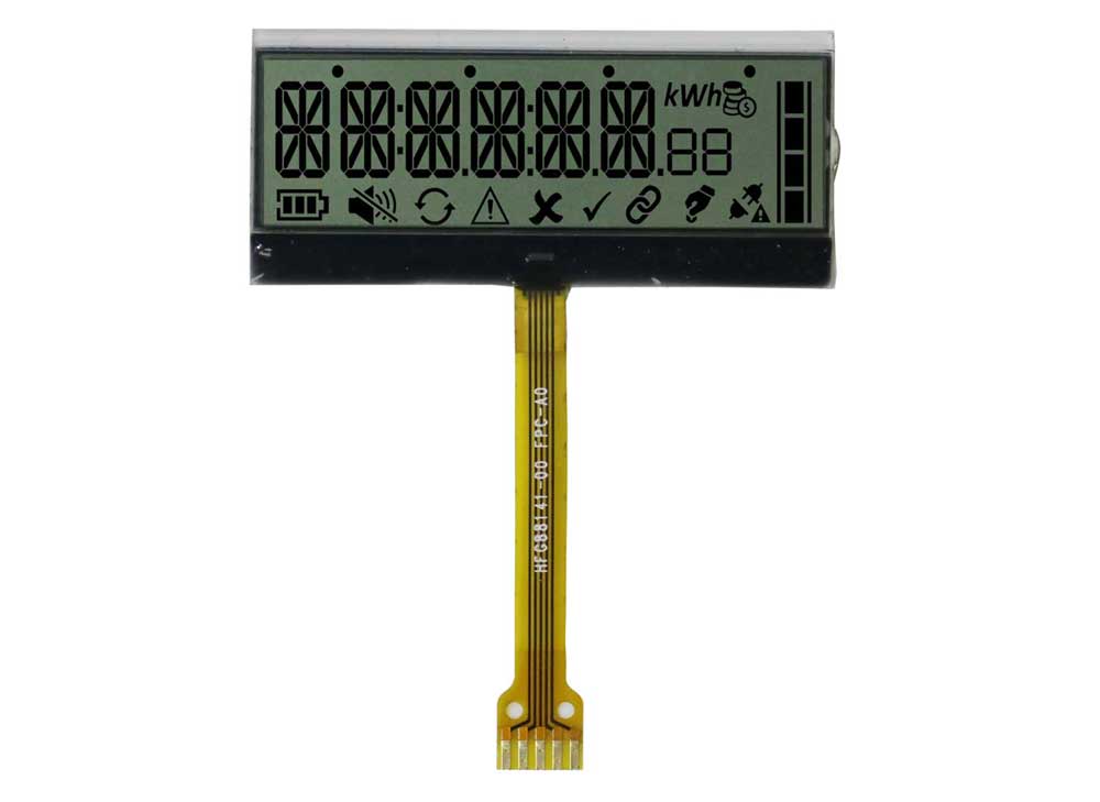
The chip still needs its specified supply, signals and supporting circuitry. A COG module may use an external board or components elsewhere in the product even if it does not carry a separate driver PCB behind the LCD.
In the monochrome dot-matrix COG projects I handle, FPC is our usual external connection, and often effectively the standard route for the platform. The FPC carries power and interface signals to the host electronics; it does not relocate a glass-mounted chip onto the film.
Why a small COG module is not automatically cheaper
This was the main commercial lesson in my original article. Reducing PCB area does not necessarily reduce the total cost of a new custom design. The glass pattern and driver-bond region, FPC, backlight structure and optical tooling may all need development.
For example, an existing COB module and a fully custom COG module are not equivalent quotation baselines. A standard COG platform can also be much easier to source than a new COG design from scratch. Ask what already exists before assuming either technology has the lower development charge.
The original examples compared 1,000 pieces with cumulative quantities such as 100,000 or 1 million to explain development-cost allocation. These illustrate the principle, not standard DisplayMan MOQ values or forecasts. A non-recurring charge has a larger effective contribution per unit at low quantities, while repeat production spreads that charge across more units.
For a project with small available space and an appropriate platform, COG can be a practical route. Review the glass ledge, FPC exit, bend space, backlight and mounting as a complete assembly.
COF: Driver Chip on a Flexible Film Circuit
In COF, the chip is mounted on a flexible film circuit, which then connects into the display system. The film is an electrical carrier, not a conveyor belt.
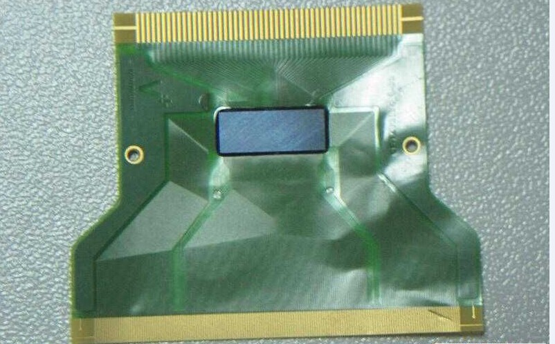
COF is an established display-packaging approach. My original statement that few people make it was too broad. What I meant was that it was uncommon among the custom monochrome module projects I received, where a suitable COB or COG solution was usually the more practical starting point.
A new custom COF route should be evaluated against actual driver availability, film interconnect requirements, bonding capability, tooling and production quantity. Compactness alone does not prove it is the most economical option.
For our routine custom monochrome enquiries, I usually review an available COB or COG platform first. If the mechanical or electrical requirements specifically point to COF, we need a project-level feasibility review rather than assuming a conventional FPC can substitute for it.
COG with FPC Is Not the Same as COF
This distinction prevents a common enquiry misunderstanding:
- COG with an FPC tail: the driver chip is on the glass; the flex provides the external connection.
- COF: the driver chip is on the film circuit itself.
- A flexible cable or FPC assembly: describes an interconnect, not necessarily a driver-packaging method.
The question is where the chip is mounted, not whether a flexible tail is visible in the product photograph. Our FPC / cable assembly page covers interconnect development as a separate product direction.
This distinction also matters for color TFT modules: their driver arrangement and their external FPC connection must be identified separately. Do not infer the packaging solely from the cable.
Compare Complete Module Size, Cost and Reliability
| Project factor | COB | COG | COF |
|---|---|---|---|
| Driver assembly | Board-mounted die and its protection in a typical bare-die module | Driver bonded to glass | Driver mounted on film |
| Mechanical allowance | Board outline, frame, contacts and thickness | Glass bonding ledge, host connection and flex bend space | Film routing, chip region, bond areas and bend limits |
| Development cost | Depends on existing board, glass, driver and backlight platform | Custom glass/FPC and bonding platform can be significant | Depends on suitable driver-film platform and process availability |
| Host interface | Module-specific | Module-specific | Module-specific |
| Reliability review | Bonding, encapsulation, contact pressure, board and assembly | Glass bonds, interconnect, handling and mounting | Film bonds, routing, bend strain and assembly |
| Starting direction in my monochrome projects | Useful where board-based integration fits | Useful for compact modules with an appropriate platform | Review when specific requirements justify the route |
There is no universal price, lifetime or quality ranking based only on these names. Compare the same display area, content, optical mode, interface, environment, scope of supply and order quantity.
A more compact glass assembly can still require a larger system-level mounting or connection allowance. A larger board-based module can sometimes simplify the customer’s product integration. Compare the complete product envelope.
How I Would Choose for a New OEM Project
Start with what the display must show. Fixed digits and icons point to segment artwork; changing text or graphics may require a character or dot-matrix arrangement. Then review the driver and assembly platform.
For available standard modules, check dimensions, interface, supply and lifecycle before commissioning custom work. For a custom module, ask which parts need new development and which can reuse an existing platform.
Review the following together:
- Display content: segments, icons, characters, graphics and resolution.
- Mechanical fit: outline, active area, thickness, mounting and cable exit.
- Optics: positive/negative, lighting, viewing position and contrast.
- Electronics: supply, logic levels, controller/driver, interface and host responsibilities.
- Environment: paired operating and storage ranges, humidity and assembly conditions.
- Commercial scope: sample quantity, production forecast, development charge and MOQ.
Our custom monochrome LCD quotation guide explains these requirements in detail. The ITO glass and polarizer guide covers the cell materials, electrode artwork and optical stack.
Enquiry and Sample-Approval Checklist
Send the application, intended artwork or resolution, mechanical drawing, host interface, supply, viewing position, environment and quantities. If replacing an existing module, provide its datasheet, photographs and the compatibility requirements.
Before production approval, confirm the complete module drawing and pinout, power and interface behavior, optical appearance, backlight requirements, mounting and interconnect strain. Establish acceptance conditions and verify a representative assembly.
A photograph can help identify a likely structure, but it does not establish the pinout, interface, driver lifecycle or the full production specification. The final quotation should define exactly what the supplier provides and what the host product must implement.
Frequently Asked Questions
Is COB obsolete?
No. It remains a useful architecture when a board-based module fits the product. Choose against the actual integration and supply requirements.
Does COG mean there is no PCB anywhere in the system?
No. The display driver is mounted on glass, but support electronics and host interfaces may still need a board or other components.
Does a visible FPC mean the module is COF?
No. A COG display can have an FPC connection. In COF, the driver chip itself is mounted on the film.
Is COG always cheaper at high quantities?
Not necessarily. Higher quantities can spread development charges, but the actual platform, materials, yield, assembly scope and lifecycle still determine cost.
Which technology is most reliable?
There is no universal winner from the packaging name alone. Review the qualified design, manufacturing process, mechanical integration and application conditions.
From guide to product
Explore Related Display Products
Choose the product direction that matches the visible content, hidden assembly and integration needs.
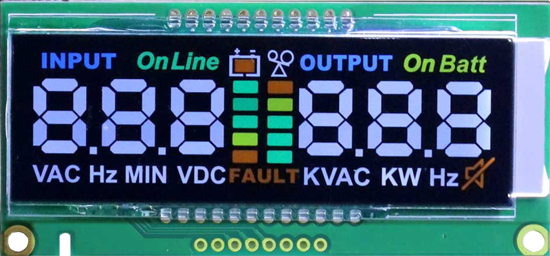
COB LCD Displays
Review board-based monochrome modules and complete assembly requirements.
Explore product options →COG LCD Displays
Review glass-mounted driver modules, interface and FPC integration.
Explore product options →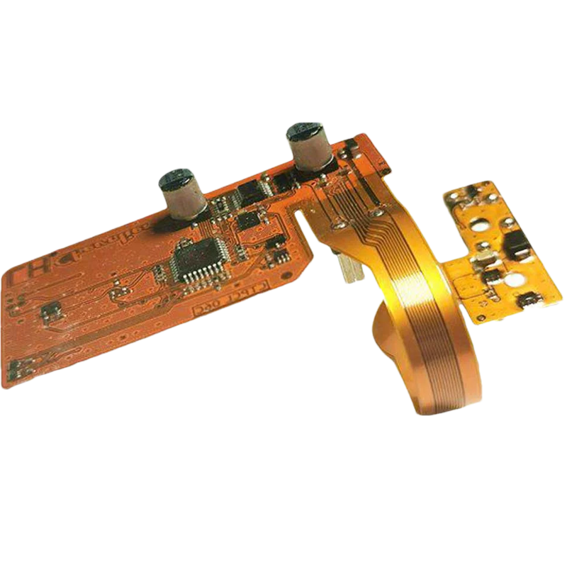
FPC / Cable Assembly
Review the interconnect separately from the driver-chip packaging method.
Explore product options →Project review
Review Your LCD Module Requirements
Send your artwork or resolution, outline, thickness, interface, supply, environment and quantity. DisplayMan can review a practical module platform and development scope.
Prefer to open the enquiry form here?
References and Further Reading
NXP: board-area and integration considerations for COG LCD solutions · Custom monochrome LCD quotation requirements
Original photographs and practical sourcing observations come from Greg’s earlier article. Current design, driver availability, fees, MOQ and test requirements must be confirmed for each project.