Greg’s custom backlight quotation guide
What Do We Need Before Quoting a Custom LED Backlight?
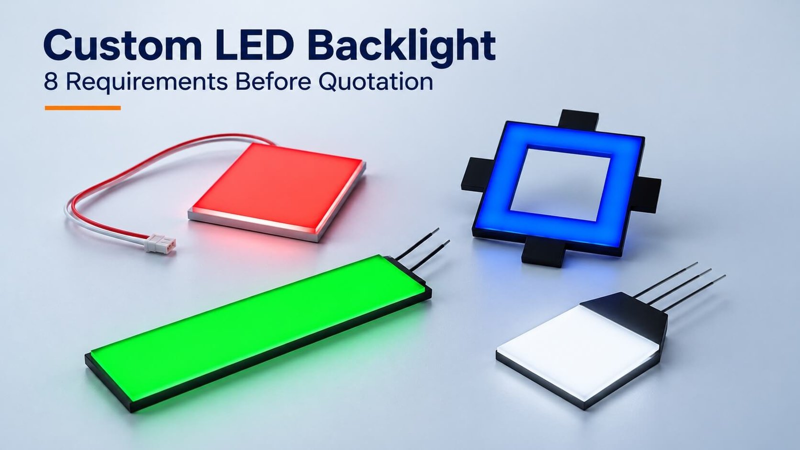
Confirm eight areas: structure, quantity, LEDs and color, thickness and optical stack, PCB/FPC, LED wiring, outline versus active area, and external connection. We can help choose the construction when you provide the application and performance requirements.
This guide combines the quotation guide with ten supporting articles and links to a separate edge-lit/direct-lit comparison: my quotation experience and the related explanations of light guides, reflectors, diffusion films, color temperature, edge/direct lighting and series/parallel wiring. Dimensions and process examples are retained with their project context.
1. Define the Backlight Structure and Application
A custom LED backlight can illuminate an LCD, an instrument panel or another optical assembly. Panel lights, light boxes and LCD backlights can share edge-lighting principles, but their optical films, luminance, thermal design, mounting and quality requirements are not necessarily interchangeable.
In my experience, custom backlights require more information for quotation than customers initially expect. Two parts with the same outline can have very different costs because of their light guide, LEDs, films, board, wiring and tooling. I treat the backlight as a complete custom assembly rather than a standard light source selected only by length and width.
You do not need to choose the construction before contacting us. Explain what the product must achieve and we can review a suitable arrangement.
Edge-lit or direct-lit: tell us the requirement first
Edge-lit backlights place LEDs along a light-guide edge; direct-lit or bottom-lit backlights place an LED array behind the illuminated area. You do not need to choose the construction in advance. Send the required thickness, useful brightness, uniformity, space, power and quantity so we can review a feasible direction.
For the complete structure comparison, original photographs and practical selection examples, read our Edge-Lit vs Direct-Lit LED Backlights guide.
Why LED Became the Standard: CCFL Comparison and Eight Practical Advantages
LED is the normal starting point in the LCD backlight projects I handle today. My earlier CCFL comparison was written during the transition from fluorescent tubes to LED. Its useful engineering lessons remain relevant, although its market forecasts should no longer be read as descriptions of a transition still to come.
LED versus CCFL Backlighting
CCFL means cold-cathode fluorescent lamp. It uses a fluorescent tube and a suitable high-voltage AC inverter. LED uses semiconductor emitters with current-controlled drive. Both need a complete optical assembly, and neither technology name alone guarantees color quality or useful front luminance.
| Comparison | CCFL | LED |
|---|---|---|
| Source and geometry | Fluorescent tube with tube-length and mounting constraints | Small emitters arranged along edges or behind the illuminated area |
| Drive | Matching AC inverter and lamp-starting requirements | Current-controlled strings or branches; driver voltage depends on the arrangement |
| Thin construction | Tube diameter, reflector and connections constrain the stack | Compact sources support thin designs, subject to optics and thermal requirements |
| Brightness and switching | Behavior depends on the lamp and inverter, including warm-up | Supports rapid electronic control, with the actual dimming behavior set by the driver |
| Local dimming | More constrained by tube layout and control | Suitable arrays and independent drivers can provide local-dimming zones |
| Color performance | Depends on the lamp spectrum and display filters | Depends on LED spectrum, conversion materials and display filters; not automatically a fixed gamut improvement |
| Materials | Contains mercury and needs appropriate handling | LED emitters do not use mercury as the light-generating medium |
| Reliability | Lamp, inverter, connections and environment matter | LED junction temperature, driver, optics, connections and environment matter |
My original text compared an older 12-inch notebook example below 3 W for LED backlighting with about 3.5–4 W for CCFL. This is retained as a historical illustration, not a present-day efficiency guarantee or a measurement of the whole computer. The original 40–60% energy-saving examples similarly need matched brightness, optics and system boundaries before they can be applied to a new project.
Fast LED control supports dimming, scanning or strobing in suitable systems. It does not by itself eliminate LCD response-time blur or black-state transmission. Local dimming reduces illumination in dark image regions; effectiveness depends on the zones, algorithms and optics. For color-display projects, see our Mini-LED backlit LCD displays.
Sequential RGB illumination without conventional color filters is a separate architecture requiring a suitably fast LCD and synchronized control. An ordinary RGB backlight is not automatically a color-filter-free display. The original switching-time, gamut and efficiency figures did not establish performance for a specified product, so they should not be used as quotation targets.
Eight Advantages That Matter in a Custom Backlight
- Compact sources. Small LED packages allow flexible placement around the required illuminated area, with source size chosen to suit the optical entrance or direct-lit array.
- Efficient use of electrical power. Suitable emitters, optics and drivers can achieve the required output economically. Compare useful luminance at the same conditions rather than assuming a fixed percentage saving.
- Long operating-life potential. LED lumen maintenance can support long use when current and temperature are controlled. Historical 60,000–100,000-hour claims are not guarantees for the entire module; define the decay criterion and operating conditions.
- Scalable brightness. We can review emitter type, current, quantity, spacing and optics. LEDs still generate heat, so increased output needs a corresponding thermal review.
- No mercury in the LED light-generating medium. This is a practical distinction from fluorescent lamps, without implying that every material in an LED module is harmless, recyclable or automatically compliant.
- Solid-state construction. There is no fragile fluorescent tube or hot filament in the emitter. The PCB, solder joints, flex, connectors and films still need mechanical protection.
- Color choices. Single-color, white and RGB sources support different interfaces. Three 8-bit channels have 256 × 256 × 256 = 16,777,216 numerical combinations, but the distinguishable colors and gamut depend on the source, optics and controller.
- Electronic control. Compatible drivers can provide dimming, color mixing and synchronization with the product electronics. Network functions and programmability come from the controller, not from an LED emitter alone.
The original light-source article mixed several different wattages and conversion-efficiency figures. For an actual design, use P = V × I and the selected component/driver data rather than combining those old examples. “Cold light” does not mean zero heat, zero glare, zero radiation or an eye-health guarantee.
2. Confirm Quantity, Development Scope and Tooling
Tell us the prototype quantity, first production order, annual forecast and expected schedule. Higher repeat quantities can spread development and setup costs, but the actual price depends on the structure and production process.
A cut guide using an existing thickness is a different commercial proposition from a molded optical part with a dedicated board and special LED bin. Ask which elements can use existing materials and which require development.
My original article used a 50,000-piece LED quantity as the threshold for a particular custom color-temperature sourcing route. That referred to the LED components in our supply arrangement, not automatically 50,000 finished backlights. A current special-bin or custom LED requirement needs a fresh supplier review.
3. Select LEDs, Color and Color Temperature
For the full explanation of single-color sources, white LEDs, RGB mixing, driver control and fixed colored artwork, read our LED Backlight Colors: White LEDs, RGB Mixing & Control guide.
My original designs commonly used DIP LEDs or SMD LEDs. The right package depends on the light-entry geometry, current, color, mechanical space and assembly route. Higher-power emitters need a suitable optical and thermal design rather than simply being substituted into a thin guide.
Specify white, a single color or RGB. For RGB, say whether the whole area changes color together or different regions need independent control. For a printed multicolor interface, identify which colors are fixed artwork and which are electronically controlled.
What color temperature means
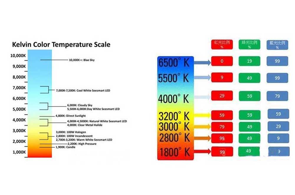
For white LEDs, correlated color temperature (CCT) describes the white appearance relative to the color of a heated reference radiator. The unit is kelvin (K), without a degree symbol. A lower CCT generally appears warmer; a higher CCT generally appears cooler. It does not mean that the LED is physically operating at that temperature.
| Illustrative white-light description | Approximate reference | Selection point |
|---|---|---|
| Warm white | Often around 2,700–3,500 K | Confirm the intended appearance rather than the marketing name |
| Neutral white | Often around 4,000–5,000 K | Approve a measured target and sample |
| Cool/daylight white | Often around 6,000–6,500 K or higher | Confirm bin and tolerance |
| Display white reference | D65 is approximately 6,500 K | Chromaticity matters as well as the CCT number |
These names are not universal bin boundaries. My old table called all values below 6,000 K “warm white”; that is too broad for an engineering specification.
The original background article included familiar lighting examples: sunrise around 2,000 K, tungsten photography around 3,200 K, electronic flash around 5,500 K and overcast daylight around 6,500–8,000 K. These are illustrative appearances, not fixed values at a particular number of minutes after sunrise. Weather, location and light-source design change the result.
Specify more than a Kelvin number
Two LEDs with the same nominal CCT can still look different. Where color consistency matters, provide chromaticity targets or an approved bin/tolerance and a reference sample. Check the light through the actual LCD, films and cover because those layers can shift the finished white appearance.
My practical preference is to evaluate available bins before requesting a special LED production run. I cannot assume that every requested white point is available economically at a small quantity. The original claims linking white-point preference to eye color or nationality are not a basis for product selection.
4. Define the Complete Thickness and Optical Stack
Thickness is one of the first constraints I ask about. It affects LED packaging, the guide, circuit carrier, diffusion and assembly allowances.
| Original edge-lit project layer | Example thickness |
|---|---|
| Reflector | 0.1 mm |
| Light guide | 0.6 mm |
| Diffusion film | 0.1 mm |
| Double-sided adhesive allowance | 0.1 mm |
| Complete example | Approximately 0.9 mm |
This preserves my original 0.9 mm backlight example. It does not establish a universal minimum. Other adhesive arrangements, mounting features and connections can change the complete envelope.
Common guide thicknesses recorded in my projects included 1.0, 1.5, 2.0, 2.5, 3.0, 3.5, 4.0 and 5.0 mm. A dedicated guide as thin as 0.45 mm was also discussed as a special development direction; that is not the same structure as the 0.6 mm guide used in the 0.9 mm assembly above.
In our earlier DIP construction, a guide thickness of around 2.0 mm or more was needed to accommodate the chosen source. Thinner guides led us to SMD and PCB/FPC arrangements. This is a package-dependent design constraint, not a universal limit of every DIP or SMD component.
Practical Layer and Source Allowances
My older basic-structure article often started with 2.5–3.5 mm guides and cited about 2 mm for its selected DIP arrangement. It also used shielding allowances above 7 mm for one DIP layout and above 4 mm for an SMD layout. These are specific earlier layouts, rather than contradictions to be resolved by imposing a universal minimum on all designs. Approve the actual light-entry region, mask and connection envelope.


Light guide plate: what it does
A guide transports and extracts light. The PMMA plate itself is not the light source. LED light is coupled into it and extraction features make the face appear illuminated.
Optical-grade PMMA, also called acrylic, is a common material. My original material notes recorded a density of about 1,190 kg/m³ and light transmission around 92% for suitable clear material. Those are material reference figures, not the useful optical efficiency of a complete backlight. Surface finish, thickness, wavelength, contamination and processing all matter.
I pay attention to material consistency because unsuitable or poorly controlled acrylic can have color, transmission or aging problems. Recycled content alone does not replace a proper material specification and validation. Other optical polymers, including COP, may be appropriate for particular requirements; the old article’s supplier prices and predictions about adoption are not current quotation evidence.
Flat, wedge, printed and molded guides
| Classification | Options and meaning |
|---|---|
| Profile | Flat or wedge-shaped; a wedge changes thickness across the guide |
| Extraction features | Printed dots or non-printed surface/internal structures |
| Pattern processes | Printed patterns, machining/V-cut, etching, replicated or molded features, according to the design |
| Forming route | Cut sheet or injection-molded optical part |
| Illumination architecture | Edge-lit guide versus direct-lit mixing optics; these are not printing-method classifications |


Cut-sheet manufacturing and factory examples
In the original factory examples, large PMMA sheets were approximately 3.5 × 1.5 m. The process involves preparing the outline and optical surfaces, creating the designed extraction pattern, cleaning, and inspecting the finished optical part. A printed pattern also needs suitable curing and adhesion control.


IR/thermal and UV-curing are process choices for suitable ink systems. The original table compared brightness, adhesion, curing speed and process consistency; those are useful evaluation criteria. However, UV does not inherently mean low brightness or poor adhesion, and IR does not guarantee higher performance. Test the selected ink, substrate, pattern and cure conditions.
Source Choice, Heat and Uniformity
The historical basic-structure article also compared bulbs, fluorescent lamps, EL and other emissive technologies. These are background alternatives, not a current product-selection table: its incomplete power/lifetime units and values cannot support direct engineering comparison. For a focused explanation, see our EL vs LED backlight guide.
Thin construction, improved useful output and consistent production remain valuable goals, but printed and non-printed guides should be compared against the actual specification rather than assuming one always replaces the other. Scratches, bright/dark stripes, optical feature accuracy and mechanical strength deserve sample inspection. Original V-cut uniformity examples of 75% versus 85% do not establish universal performance levels.
Thermal testing should continue until the representative assembly reaches a stable operating condition. The original discussion described rapid heating during the first 20 minutes of one 32-inch example, followed by slower change. That observation is not a fixed stabilization time for every module; enclosure, ambient, power and thermal path all matter. Check luminance and color as well as temperature.
Injection molding and dedicated tooling
An injection-molded guide can incorporate the required outline and extraction features, or use a subsequent printed pattern. It requires a suitable optical tool, material and process control.


I remember trying to lift one of the heavy steel tools in the original factory visit and finding it too heavy to lift on my own. Tooling is a real development item, not merely a charge added to an otherwise identical cut plate.
The original discussion mentioned tooling from around US$1,000. Treat this as a historical cost example rather than a current minimum or price promise. A mold can support repeatable geometry and designed optical features, but molding does not automatically improve transmission or brightness for every part.
V-cut and other microstructured optics can redistribute light toward the intended viewing direction. Evaluate on-axis output together with angular distribution. The old article’s 30% improvement, yield, market-share and patent statements lacked the project and date context needed for current decisions, so they are not used as universal specifications here.
Reflector: return light to the useful optical path
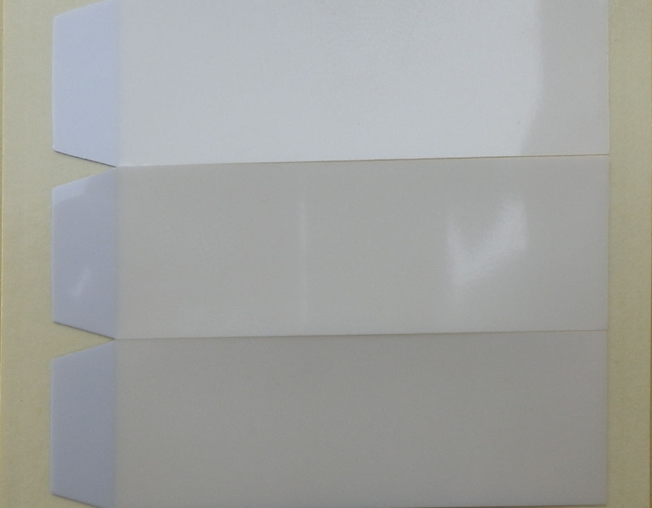
A rear reflector redirects light that would otherwise leave the back of the assembly. Select the actual backlight-grade material by spectral reflectance, thickness, diffuse/specular behavior, temperature stability, electrical clearance and assembly requirements.
The original reflector article discussed three coating families: metal, dielectric and metal–dielectric. Metals can reflect across broad wavelength ranges but also absorb light; oxidation or tarnishing can affect performance. Protective coatings may be needed.
Its examples included aluminum and silver for visible applications and wavelength-dependent uses of other metals such as gold or copper. Silicon oxide, magnesium fluoride and aluminum oxide were mentioned as protective or optical layers. These are optical-coating background examples, not a recipe for the film in every LCD backlight.
Dielectric multilayers use refractive-index contrast and interference; alternating high- and low-index layers can be designed for selected wavelengths and angles. A quarter-wave stack is one design concept, not the structure of every reflective sheet. Metal–dielectric coatings combine the approaches and may alter spectral neutrality.
A commercial backlight reflector may instead be a white polymer-based or other engineered optical sheet. Do not substitute building insulation foil simply because an old article quoted high radiant-heat reflectance. Likewise, an anti-reflection coating reduces unwanted surface reflection; it is not a rear reflector and does not work simply by “increasing diffraction.”
Diffusion film: balance uniformity and transmission
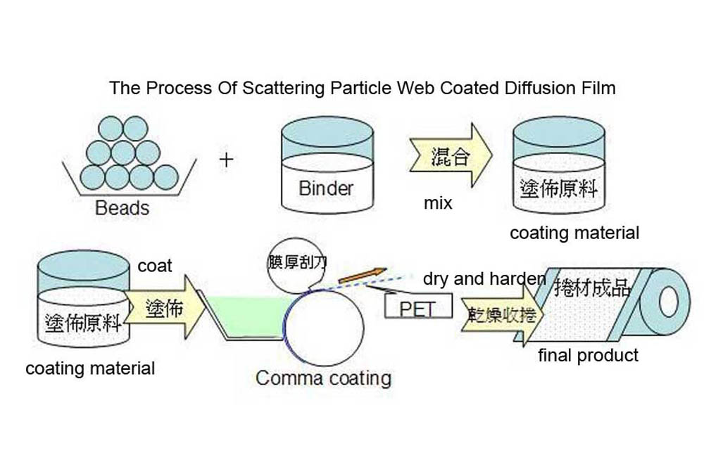
Diffusion redistributes light to reduce visible LED points and guide-pattern artifacts. It uses scattering from particles, surface structures or other optical features. More diffusion is not automatically better: useful luminance and angular distribution change too.
The original article described coated and non-coated films, with particle-coated and UV-replicated microstructure approaches. A typical construction may include an optical substrate, a diffusion layer and a protective, spacing or adhesive-related layer. Actual stacks vary.
PET substrate figures originally listed 5, 38, 50, 75, 100, 125, 150 and 188 µm. Retain these as historical source-list values, especially verifying the 5 µm entry before specification; substrate thickness is not necessarily complete coated-film thickness.
Particle coatings may use inorganic or polymer particles in a resin binder. Coating uniformity, particle distribution, adhesion, solvent handling and curing are important process checks. In a UV-replicated route, a structured roller transfers a microstructure into a photosensitive coating before curing.
Some assemblies use more than one diffusion layer at different positions, but two diffusion films are not mandatory for every LCD. Select the film stack against hot spots, luminance, angular output, handling and cost. A brightness-enhancement/prism film has a different primary optical role from a diffuser.
Optical Films in the Complete Backlight Module
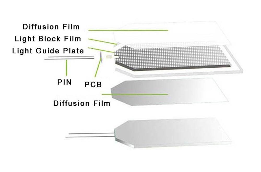
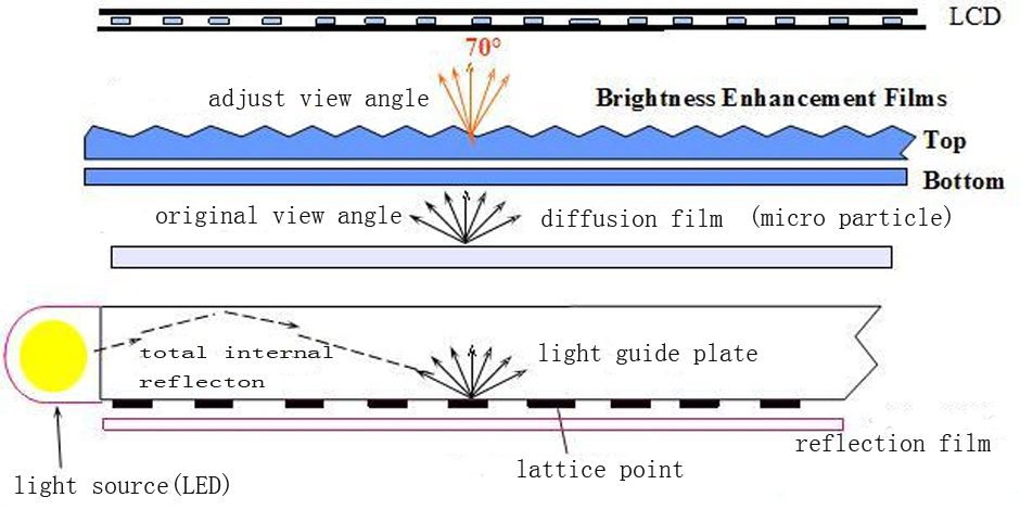
The original optical-film article brings these parts together: LEDs, the light guide where required, reflector, diffusion film, brightness-enhancement/prism film, light-shielding film and the supporting frame. They redistribute, recycle, transmit or absorb light in different ways. A useful quotation therefore defines the complete stack, not a collection of individually selected sheets.
| Part | Primary function | Quotation check |
|---|---|---|
| Rear reflector | Returns rearward light toward the useful optical path | Reflectance, spectral behavior, thickness and stability |
| Light guide plate | Transports and extracts edge-injected light | Material, extraction pattern, outline and source coupling |
| Diffusion film or plate | Redistributes light to reduce source and pattern visibility | Uniformity, transmission, haze and thickness |
| Brightness-enhancement/prism film | Redistributes angular output, often increasing useful forward luminance | Orientation, angular requirements, compatibility and luminance trade-offs |
| Light-shielding film | Masks source regions and unwanted illuminated areas | Opacity, registration, adhesive and visible window |
A prism film does not generate additional light. An increase in on-axis brightness must be evaluated with angular distribution and the complete optical system. Likewise, not every backlight needs every layer, and a direct-lit structure may use a diffuser plate rather than an edge-lit light guide.
Brightness-Enhancement Films: Prism Optics and Polarization Recycling
Brightness Enhancement Film (BEF) commonly refers to a microstructured prism film used to redistribute backlight output toward the desired viewing direction. Light that is not immediately transmitted can be returned into the optical stack and partly recycled. The result can be higher forward luminance without increasing LED input power, subject to the complete optical design.
My original article cited a roughly 70-degree forward angular region and brightness gains around 40–60% for one film. These are historical illustrative figures, not guaranteed specifications for every BEF. Compare the actual angular luminance curve and measurement conditions. Two prism films may be crossed at approximately 90 degrees to control both axes; their gains should not be simply added or multiplied.
| Optical approach | Main role | Design check |
|---|---|---|
| Conventional prism film | Redistributes angular output toward the useful direction | Prism orientation, forward gain, off-axis performance and handling |
| Multifunctional film | Combines functions such as diffusion and brightness enhancement | Whether it can replace separate layers while meeting the target |
| Microlens film | Uses lens-like structures to shape or mix light | Actual optical function and compatible stack; it is not necessarily a prism sheet |
| Reflective polarizer | Transmits the selected polarization and reflects another component for recycling | Polarization alignment, optical compatibility and measured system gain |
The earlier article grouped these under prism-sheet categories. For selection, reflective polarizers should be distinguished from conventional prism films: they work through polarization recycling rather than simply the same angular prism action. A multifunctional film is not automatically superior to separate sheets in every assembly.
Reflective Polarizers and DBEF
DBEF means Dual Brightness Enhancement Film, a 3M product family associated with reflective polarization recycling. It should not be used as the generic name for every brightness-enhancement film. In a compatible optical stack, recycled light can contribute additional useful transmitted output.
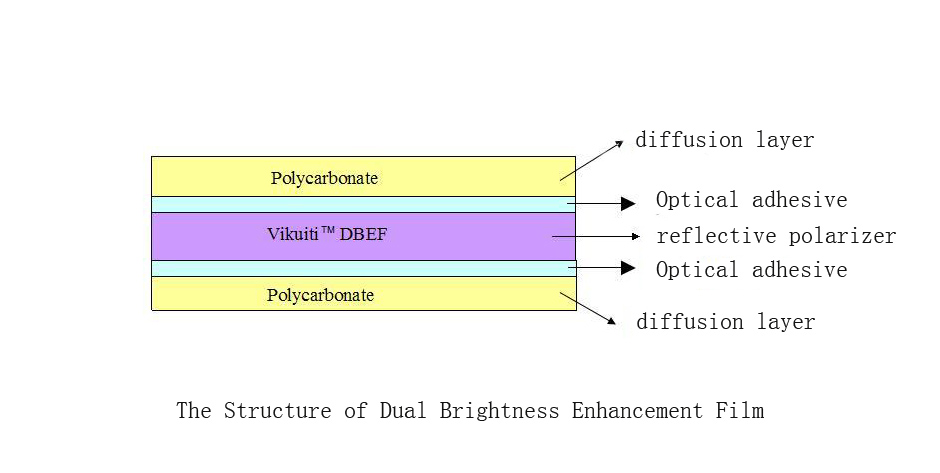
The original discussion mentioned more than 800 optical layers and a 1.6-times brightness example. Layer counts are product-specific, and many layers do not mean hundreds of distinct refractive-index materials. The quoted gain also depends on the reference stack and test geometry; it is not a universal increase for any LCD.
How Prism Films Are Manufactured
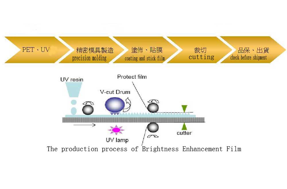
The original production explanation is worth retaining: film manufacture brings together optical design, precision tooling, resin formulation and coating or replication. A precision-patterned roller can transfer the optical microstructure into a UV-curable resin layer on a suitable substrate. Curing fixes the replicated structure.
Tooling accuracy, resin filling, shrinkage, coating consistency and surface cleanliness affect the final result. Prism films redistribute light; they do not automatically increase both viewing angle and on-axis brightness at the same time. Check the balance required by the product.
The original supplier list included names such as 3M, Mitsubishi Rayon, MNTech, Shinwha, DNP, E-fun, SKC Haas and several Korean electronics or chemical companies. It records the article’s historical background, not a verified current supplier directory, market-share statement or approved procurement list. For quotation, specify the actual film grade or required optical performance rather than choosing only by a historical company name.
BEF and reflective polarizers can represent a meaningful share of optical-stack cost, but neither is always the most expensive backlight component. Evaluate the gain, angular appearance, thickness, reliability and cost in the finished stack.
Optical Loss: Backlight Output Is Not Finished LCD Brightness
My original article quoted an illustrative light budget: about 60% reaching the polarizer after the backlight optics, and about 4–8% finally passing through the LCD/polarizer system. The original system, denominator details and test report were not supplied. These historical figures explain why optical loss matters; they are not a calculation rule for a new display.
For quotation, state the required brightness at the measurement surface. A backlight-surface target and a finished-LCD target can require very different LED output. Measure the intended guide, films, LCD and cover together rather than applying a fixed transmission percentage to every panel.
Original Backlight Cost Breakdown: Historical Reference
The following table is retained from the original optical-film article. Figures are recorded percentage shares for the illustrated historical constructions, not present-day prices or a prediction for a new custom backlight. The source date, exact BOM and measurement basis were not recorded. A zero light-guide share reflects that table’s construction, not a claim that all backlights of that size omit a guide.
| Component / size (inches) | 15.4 | 17 | 26 | 32 | 40–42 | 46–47 |
|---|---|---|---|---|---|---|
| LED | 9 | 17 | 23 | 22 | 19 | 23 |
| Light guide plate | 10 | 12 | 0 | 0 | 0 | 0 |
| Diffusion film | 13 | 8 | 13 | 17 | 19 | 18 |
| Reflection film | 6 | 6 | 2 | 5 | 3 | 2 |
| Brightness-enhancement/prism film | 25 | 12 | 11 | 9 | 24 | 20 |
| Outer frame | 12 | 13 | 8 | 7 | 5 | 5 |
| Other materials | 25 | 32 | 43 | 40 | 30 | 32 |
| Total | 100 | 100 | 100 | 100 | 100 | 100 |
The original discussion also cited backlight shares of around 20–30% of LCD panel cost, including 20–25% for some 15–17-inch constructions and more than 25% for some 30-inch-and-larger constructions. It described optical films as about 40% of a backlight cost. These are historical examples with different scopes, not universal cost ratios. The table itself shows how the component mix changes between constructions.
My practical takeaway is unchanged: optical-film selection can materially affect both performance and price. Compare complete BOMs and approved optical results instead of assuming that a larger panel always has the same cost proportions or that its backlight must be its most expensive component.
5. Choose PCB or FPC and Connection Placement
For the very thin guide in my original example, a conventional rigid-board mounting arrangement did not fit, so we needed a dedicated FPC. A dedicated flexible circuit could cost more than a conventional board in that project, but it made the required structure feasible.
Tell us where the LED board, pins or wires may sit. The original examples included hard pins or wires at the ends of a PCB edge. Source position, soldering access, board width and connector clearance must agree with the enclosure.
I often used 3.0 V arrangements in the earlier small-backlight projects. Requirements such as 6, 9 or 12 V could require a different LED string/board layout. These voltages are design examples, not standard ratings for every backlight.
Review our FPC / cable assembly options when the backlight needs a dedicated flexible connection. Circuit-carrier selection and external connector choice should be reviewed together.
6. Specify LED Series, Parallel or Hybrid Wiring
LED wiring affects supply voltage, current, fault behavior and brightness consistency. “Parallel is common” in my small-module examples does not mean it is the best arrangement for every size.
| Arrangement | Main electrical relationship | Benefit | Design check |
|---|---|---|---|
| Series | Same current through the string; forward voltages add | Straightforward string current control | Driver voltage/headroom and open-string behavior |
| Parallel | Branches share supply voltage; currents add | Separate branches can remain active if one opens | Branch current regulation or balancing |
| Series–parallel | Multiple series strings in parallel | Practical voltage/current compromise | Current balance and fault response for each branch |
For example, four series LEDs operated at a nominal 3 V each and 20 mA require roughly 12 V across the LEDs at 20 mA, plus driver headroom. Four comparable parallel branches require roughly 3 V at a combined 80 mA, plus appropriate current control. Real forward voltages and ratings must come from the selected parts.
Series faults
An open LED normally interrupts its series string unless a designed bypass path is present. A shorted LED stops emitting but can allow the remaining string to operate under a suitable constant-current driver, subject to driver compliance and fault settings. With an unregulated voltage source, current can rise when string voltage falls.
The original article mentioned a Zener bypass across each LED. A bypass device needs its own threshold, power and fault analysis; adding an arbitrary Zener is not a universal fix.
Parallel branches and shared current
LEDs do not necessarily share current evenly just because they share voltage. Forward-voltage differences and temperature can cause current imbalance. Use a suitable resistor, current regulator or other balancing arrangement for each branch where needed.
If a single regulator forces a fixed total current into unregulated parallel branches, an open branch can increase stress on the remaining branches. This is the useful concern behind my original warning. It does not mean that all constant-current parallel designs should be rejected: multichannel current-regulated drivers are an appropriate solution in many systems.
Hybrid connections
Series strings connected in parallel and parallel groups connected in series have different fault paths. Driver topology and protection determine the result; one short does not inevitably burn out every remaining LED. Do not rely on a failed LED eventually burning open, or simply add more LEDs as a substitute for current regulation.
For quotation, provide the supply range, desired current or power, LED/string arrangement if fixed, dimming and required fault behavior. If these are undecided, ask us to review the circuit direction.
7. Separate Outline, Active Area and Light-Shielding Area
The original example used a 30 × 30 mm outline, 25 × 30 mm active area and 1.9 mm total thickness, with a 1.5 mm guide in that assembly.
It also described a 4 × 30 mm masked region. Do not infer all allowances by subtracting active area from the outline: the original nominal figures do not define every margin. A drawing should separately dimension the illuminated window, source mask, outline, connection and mounting features.
My earlier starting allowances were about 5–7 mm of shielding for the selected DIP arrangements and 3–5 mm for the selected SMD arrangements. These are useful experience-based starting points, not guaranteed minimums for every source and brightness target.
For non-rectangular products, see our round and ring LED backlight design examples. They show why the illuminated shape and complete assembly outline can differ.
8. Confirm the External Connection and Integration Requirements


My original list included wire harnesses, PCB pads with or without hard pins, FPC, metal pins and simple wire leads. Wires and metal pins were common in the projects I handled. Specify pinout, cable length, connector model, polarity, strain relief and permitted exit position.
A drawing should also identify adhesive surfaces, keep-out areas, film orientation and permitted mounting pressure. Avoid making the final housing clamp distort the optical stack or expose the source region.
Two backlights with the same outline can therefore have very different unit prices: one may use a cut guide, available LEDs and wire leads; another may need a dedicated guide tool, special source bin and custom FPC. That is why these eight requirement areas make an accurate quotation much easier.
Final Enquiry Checklist and Sample Approval
| Requirement | Information to send |
|---|---|
| Application | LCD illumination or other use; indoor/outdoor environment and duty cycle |
| Geometry | Outline, illuminated area, mask, thickness, mounting and drawings |
| Optical target | Luminance and measurement surface, uniformity, color/CCT and tolerance |
| Electrical | Supply range, current/power, dimming, driver and fault requirements |
| Materials | Any mandatory guide/film/board material or approved sample |
| Connection | Wires, pins, PCB pads, FPC or connector with pinout and exit |
| Commercial | Sample and order quantities, annual forecast and schedule |
Approve the sample through the intended LCD and cover where possible. Check the same measurement locations and conditions across samples, and confirm brightness, uniformity, color, current, thermal behavior and mechanical fit. This is more useful than comparing photographs taken with different exposure or white-balance settings.
Frequently Asked Questions
Do I need to choose edge-lit or direct-lit before requesting a quote?
No. Send the visible area, available thickness, output target and integration requirements. We can review the construction direction.
Does specifying 6,500 K guarantee identical white appearance?
No. Confirm the LED bin or chromaticity tolerance and approve the complete optical stack against a reference sample.
Can I remove the reflector or diffuser to reduce thickness?
Sometimes the optical structure can be redesigned, but removing a layer can change efficiency, uniformity and angular output. Evaluate the complete result.
Is 0.9 mm a universal minimum thickness?
No. It is one of my project examples using a 0.6 mm guide and a particular film/adhesive arrangement.
Does a 50,000-piece LED quantity mean 50,000 complete backlights?
No. The historical figure concerned a particular custom LED sourcing arrangement. Current component MOQ and finished-assembly MOQ must be quoted separately.
From guide to product
Explore Related Display Products
Choose the product direction that matches the visible content, hidden assembly and integration needs.
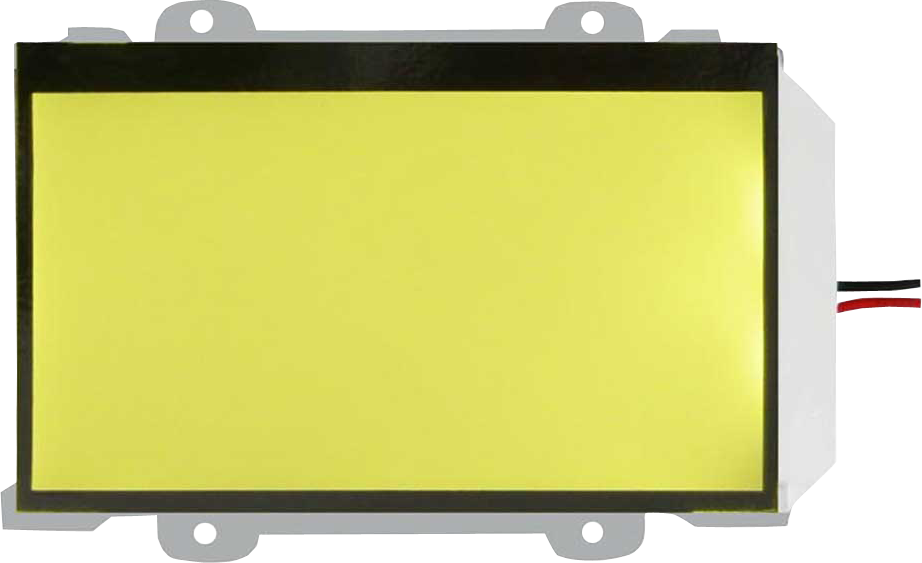
LED Backlights
Review custom shapes, optical targets and electrical arrangements.
Explore product options →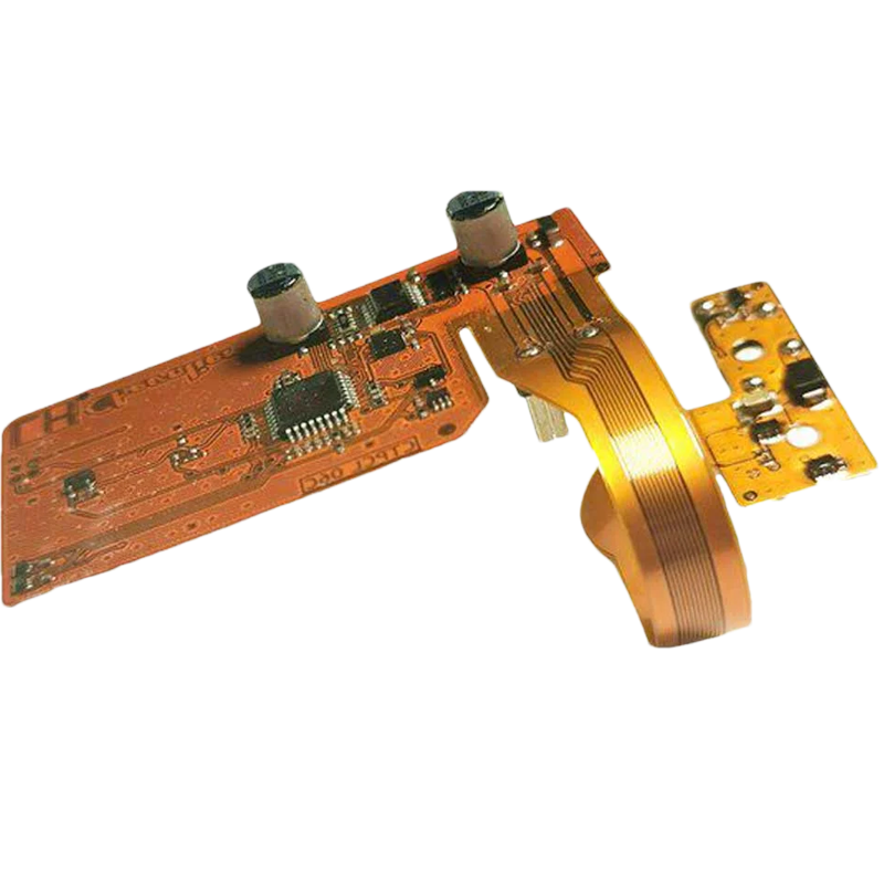
FPC / Cable Assembly
Review flexible circuit and connection requirements where the backlight structure needs them.
Explore product options →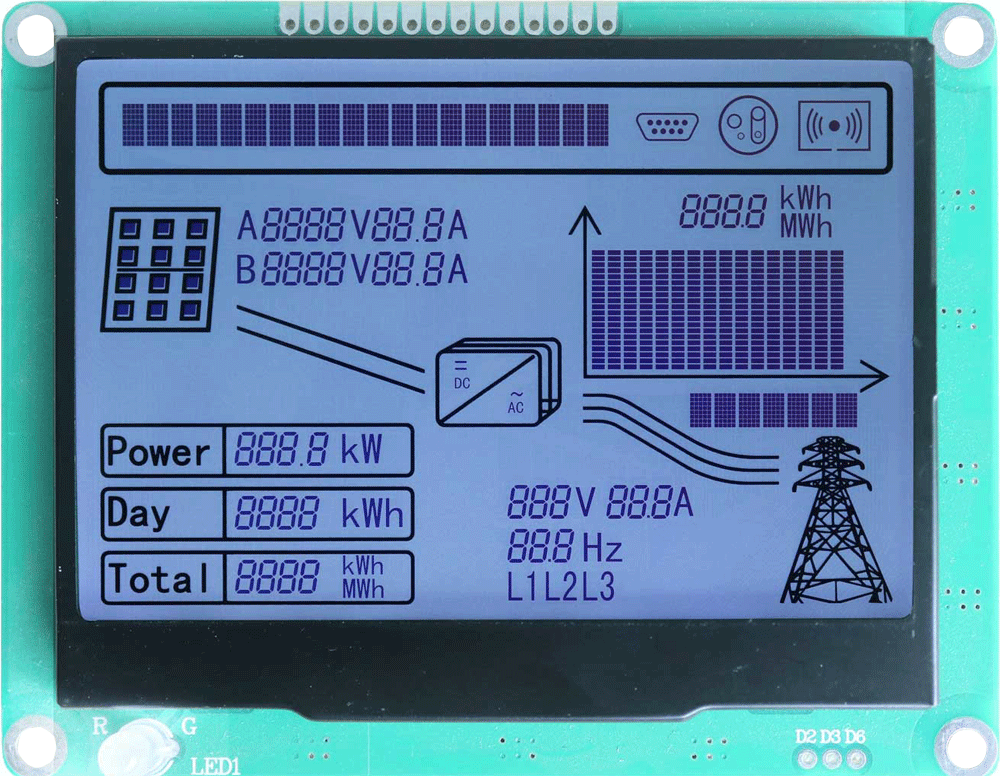
Monochrome LCD Displays
Develop the illumination together with a segment or dot-matrix LCD assembly.
Explore product options →Project review
Review Your Custom LED Backlight Requirements
Send your drawing, illuminated area, thickness, brightness, color, supply and quantities. DisplayMan can review the optical structure, electronics and development requirements.
Prefer to open the enquiry form here?
Related DisplayMan Guides
Round and ring LED backlight designs · EL vs LED technology comparison · Custom monochrome LCD quotation requirements
Original factory photographs, dimensions and sourcing examples are retained from Greg’s articles. Historical market statistics, unsupported legal claims and obsolete generalizations have been removed; current projects require approved specifications.